QUICK START INSTRUCTIONS
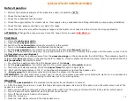
Before Operation
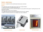
1 - Perform the hardness analysis of the water to be used, it should be
“
0
”
0
F
.
2 - Check the fuel line for fuel.
3 - Check the condensate tank for water .
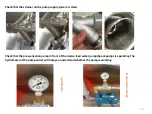
4 - Check the supply system for closed valves. (Fuel supply valve, condensate tank filling installation, pump supply installation)
5 - Check the feed pump connections (oil, water) for leaks.
6 - Check that the oil level is within the proper range and that water is not mixed into the oil from the oil pump dipstick.
ATTENTION !
Change the pump oil every 3 months. Type of oil to be used
(
SAE 90 GL 4
).
First Start
1
–
Close the
main vapor valve
.
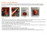
2 - Open the
trap bypass valve
.
3 -
Switch on the
main switch
and supply electricity to the system.
4 - Turn on the
burner switch
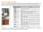
on the electrical control panel.
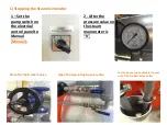
5 - Set the
pump switch
on the electric control panel to the first start (
Manuel
) position.
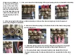
6 - Observe the operation of the pump. The pump will start to fill the coil. Continue this process until the water comes in from
the
first start-up valve (Bypass)
.
ATTENTION!
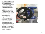
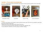
Check the pump pressure from the
pressure gauge
on the pump during the initial filling. The pressure should be
between
1-3 bars
depending on the steam generator capacity. If higher pressures are encountered, this is an indication that the
coil (serpentine)
has started to block.
7 - You should see water coming from the bypass valve of the
traps
.
8 - Set the
pump switch
on the control panel to the normal operating (
Otomatik
) position.
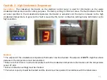
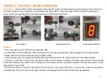
9 - The burner will start operating. Check the
burner flame
through the sight glass.
10 - Wait until the temperature is 105
°
C on the steam thermometer and close the bypass valve.
11 -
Slowly open
the main steam valve and introduce the steam into the process.
ATTENTION!!!
The first start valve is kept open to check if the steam generator coil is filled with water. Do not activate the
burner until you see that water is coming in a full way out of the start-up valve.
Stopping
1 - Move the
pump switch
on the electrical control panel from automatic to manual.
2
-
After the pressure value is 0, open the trap valve group bypass valve and let the pump run until water comes out of the
bypass valve outlet.
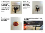
3 - When you see water coming out of the bypass valve outlet, turn the pump control switch off via the electric control panel.
4 - Turn the burner control switch off via the electric control panel.
5 - Turn off the main switch and cut the power.
6 - Close the fuel valve.
7 - Close the main steam valve and the trap bypass valve.
48
Summary of Contents for SHS Series
Page 10: ...Steam Distribution Connection Diagram 10 Buhar Da l m Kollekt r...
Page 12: ...Condensate Return Connection Diagram 12...
Page 15: ...15 Vent Connection and Blowdown Connection Diagram...
Page 55: ...55...
Page 56: ...56...

