background image

2

LOCATION OF YOUR JENN-AIR APPLIANCE

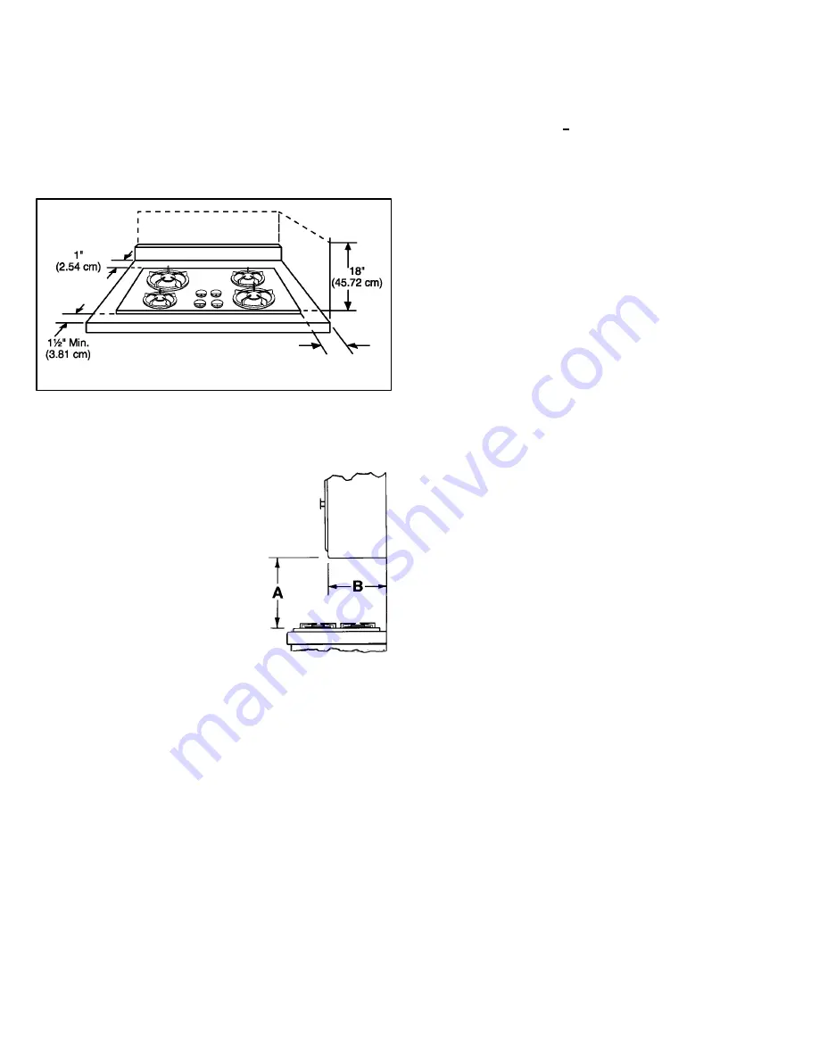
Locate this appliance away from combustible materials such as window

curtains and combustible wall decorations.
Minimum horizontal clearance between the edge of the appliance and

combustible construction extending from the cooking surface to 18

²

(45.72

cm) above the cooking surface is

1

²

(2.54 cm) at rear

4

²

(10.16 cm) at sides

(Dimensions apply to both 30

²

and 36

²

wide models)

FIGURE 1

4

²

(10.16 cm)

INSTALLING CABINETRY OVER YOUR

JENN-AIR COOKTOP

FIGURE 2

A = 30

²

(76.2 cm) minimum vertical

clearance between cooking surface and

construction above the appliance. This

clearance may be reduced to not less

than 24 inches (60.96 cm) by protecting

the underside of the combustible material

or metal cabinet above the cooking

surface with not less than 1/4 inch (.635

cm) insulating millboard covered with

sheet metal not less than 0.0122 inch

thick*

B = 13

²

(33.02 cm) maximum depth of

cabinets installed above cooking top.

Avoid use of cabinets above cooktop for storage space to eliminate

associated potential hazards such as reaching over open flames.

PREPARATION OF COUNTERTOP

The countertop cutout must be prepared according to the illustration on

page 1 of these instructions.

CAUTION:

Cutout dimensions are critical. Dimensions must be measured

and cut accurately to  1/16

²

(.159 cm) to ensure proper fit.

* Jenn-Air Over-the-Range microwave ovens (model #M418 and M438)

have been listed by UL for use over Gas and Electric Ranges. When

properly installed at a minimum height of 66 inches (167.64 cm) from the

floor to the top of the microwave, the clearance to the cooking surface at

the center will be 13-3/4 inches (34.93 cm).

IMPORTANT PREPARATION SUGGESTIONS

1. Chamfer all exposed edges of decorative laminate to prevent damage

from chipping.

2. Radius corners of cutout and file to insure smooth edges and prevent

corner cracking.

3. Rough edges, inside corners which have not been rounded and forced

fits can contribute to cracking of the countertop laminate.

4. Countertop must be supported within 3

²

(7.62 cm) of cutout.

Summary of Contents for CCG2423 Guide

Page 1: ...CUTOUT DIMENSIONS ARE CRITICAL 36 MODEL 30 MODEL INSTALLATION MANUAL SEALED GAS COOKTOPS CCG2423 AND CCG2523 JGC7430 AND JGC7536 SPECIALWARNING Improperinstallation adjustment alteration service main...

Page 2: ...d above cooking top Avoid use of cabinets above cooktop for storage space to eliminate associated potential hazards such as reaching over open flames PREPARATION OF COUNTERTOP The countertop cutout mu...

Page 3: ...oper pressure range S If this is a 36 wide model or if it is a 30 wide model and no other appliance is to be installed in the cabinetry below it proceed as instructed under paragraph I S If this is a...

Page 4: ...oin a manual shut off valve in an accessible location in the gas line ahead of the appliance regulator and external to the appliance for the purpose of turning on or shutting off gas to the appliance...

Page 5: ...thread Connection requires flare union adapters IMPORTANT Apply a non corrosive leak detection fluid to all joints and fittings in the gas connection between the supply line shut off valve and the ran...

Page 6: ...0XXXismountedbelowthisappliance andif thepower outlet for this appliance is to be located in the cross hatched area of figure 6 it is recommended the power cord be routed through the external vertical...

Page 7: ...driver over the orifice spud figure 7 and loosen spud by turning counterclockwise Carefully lift nut driver out of burner throat Orifice spud should be captured in the recess Repeat this step for eac...

Page 8: ...NNOT BE EASILY REMOVED TUCK THE FOLDS OF A CLOTH DISHTOWEL UNDER THEKNOB ANDPULL THETOWEL UPWARD WITH STEADY EVEN PRESSURE 3 Insert a slender thin blade screwdriver into the recess at center of valve...

Page 9: ...tallation of natural gas main spuds in their correct locations Save the orifices removed from the appliance for future use They will be needed if this appliance is again converted for use with LP gas...

Page 10: ...r are hazy and otherwise appear to have insufficient air obtain the services of a qualified service technician Specified input rates are as shown in figures 16 and 17 below FIGURE 16 4 BURNER MODEL BU...

Page 11: ...e caisson du br leur Ne pas tenter de convertir cet appareil en vue de l utilisation d un gaz autre que le type de gaz indiqu MOD LE DE 30 PO 30 po 76 2 cm 9 16 po 1 43 cm 21 po 53 34 cm Entr e du col...

Page 12: ...nstall es au dessus de la table de cuisson viter d utiliser les armoires situ es au dessus de la table de cuisson comme espace de rangement afin d liminer les dangers possibles par exemple lorsqu une...

Page 13: ...ns l armoire au dessous suivre les instructions de la section I S S il s agit d unappareil de30 pode largeuret qu unfour mural lectrique Jenn Air de mod le W30XXX ou W131 doit tre install dans l armoi...

Page 14: ...pareil et l ext rieur de la table de cuisson afin de pouvoir ouvrir ou couper l alimentation en gaz de l appareil Faire les raccords de tuyauterie additionnels requis la source d alimentation en gaz a...

Page 15: ...S CETTE TABLE DE CUISSON Coude filetage NPT de 1 2 po Adaptateur vas Raccord souple de l appareil max 5 pi Adaptateur vas R gulateur de pression de l appareil fourni respecter la direction d coulement...

Page 16: ...e W30XXX aussi pr s que possible du coin arri re gauche 3 Lorsquelemod leW30XXXest install souscet appareil et dans lecas o la prise de courant pour cet appareil doit tre install e dans la zone hachur...

Page 17: ...rne crous R p ter cette op ration pour chaque br leur FIGURE 7 ENL VEMENT DE LA T TE D INJECTEUR TUBE DE VENTURI EN ALUMINIUM SOCLE DU BR LEUR TOURNE CROUS DE 5 16 PO MORCEAU DE RUBAN CACHE COLL SUR L...

Page 18: ...L AIDE D UNE LAME DE M TAL SI ON NE PEUT PAS ENLEVER UN BOUTON FACILEMENT INS RER LES PLIS D UN CHIFFON VAISSELLE SOUS LE BOUTON ET TIRER VERS LE HAUT AVEC UNE PRESSION GALE ET FERME 3 Ins rer la lame...

Page 19: ...rver les t tes retir es de l appareil pour un usage ult rieur Ces t tes seront n cessaires si l appareil doit de nouveau tre converti l utilisation du gaz de p trole liqu fi B Retourner le capuchon du...

Page 20: ...u floues et semblent manquer d air communiquer avec un technicien de service comp tent Les figures 16 et 17 ci dessous donnent la puissance des divers br leurs FIGURE 16 MOD LE 4 BR LEURS EMPLACEMENT...

Reviews: