3
INSTALLATION OF APPLIANCE
The installation of this appliance must conform with local codes or, in the
absence of local codes, with the National Fuel Gas Code, ANSI
Z223.1--Latest Edition, or, in Canada, CAN/CGA-B149 Installation Code,
Latest Edition.
This appliance, when installed, must be electrically grounded in
accordance with local codes or, in the absence of local codes, with the
National Electrical Code ANSI/NFPA No. 70--Latest Edition, or, in Canada,
current CSA Standard C22.1 Canadian Electrical Code, Part 1.
All supply piping, except as noted, should use common National Pipe
Thread (N.P.T.). For all pipe connections use an approved pipe joint
compound resistant to the action of LP gas.
CAUTION:
Warranty is void on Jenn-Air equipment installed other than as
recommended by manufacturer.
This appliance is designed for use with the appliance gas pressure
regulator supplied with this appliance. It must be installed in the gas way
ahead of the gas manifold entrance. It is preset for use with natural gas and
must be converted, as described on page 6, for use with LP gas. (See
figures 10 and 11.)
This appliance is designed to operate at a pressure of 5 inches of water
column on natural gas or, if converted for use with LP gas (propane or
butane), 10 inches water column. Make sure this appliance is supplied with
and adjusted for the type of gas for which it is designed.
This appliance was adjusted at the factory for use with natural gas. If, at any
time, this appliance is to be used with a different type of gas, all of the
conversion adjustments described on pages 5 and 7 must be made by a
qualified service technician before attempting to operate the cooktop on
that gas. Natural gas should be supplied to theappliance pressureregulator
at a line pressure between 6 and 14 inches of water column or, if converted
for LP gas, between 11 and 14 inches.
WARNING:
If the line pressure supplying the appliance pressure
regulator exceeds 14
²
W.C. (any gas), an external regulator must be
installed in the gas line ahead of the appliance regulator to reduce the
pressure to no more than 14
²
W.C. Failure to do this can result in
malfunction and damage to the appliance.
Insure this appliance is adjusted for the type of gas supplied to it and that
the gas supply pressure to the appliance regulator is within the proper
pressure range.
S
If this is a 36
²
wide model, or if it is a 30
²
wide model and no other
appliance is to be installed in the cabinetry below it, proceed as
instructed under paragraph
I
.
S
If this is a 30
²
wide model and a Jenn-Air Model W30XXX or W131
Electric Wall Oven is to be installed in cabinetry below, proceed as
instructed under paragraph
II
.
S
Do not remove protective cap from pipe stub at manifold entrance until
ready to join gas supply piping to appliance.
NOTE:
In Canada, gas utilization codes prohibit use of street elbows. Use
standard pipe elbows and make modifications to these instructions as
necessary.
CONNECTING APPLIANCE TO GAS SUPPLY
A TRAINED SERVICEMAN OR GAS APPLIANCE INSTALLER MUST
MAKE THE GAS SUPPLY CONNECTION. Leak testing of the appliance
shall be conducted by the installer according to the instructions
given.
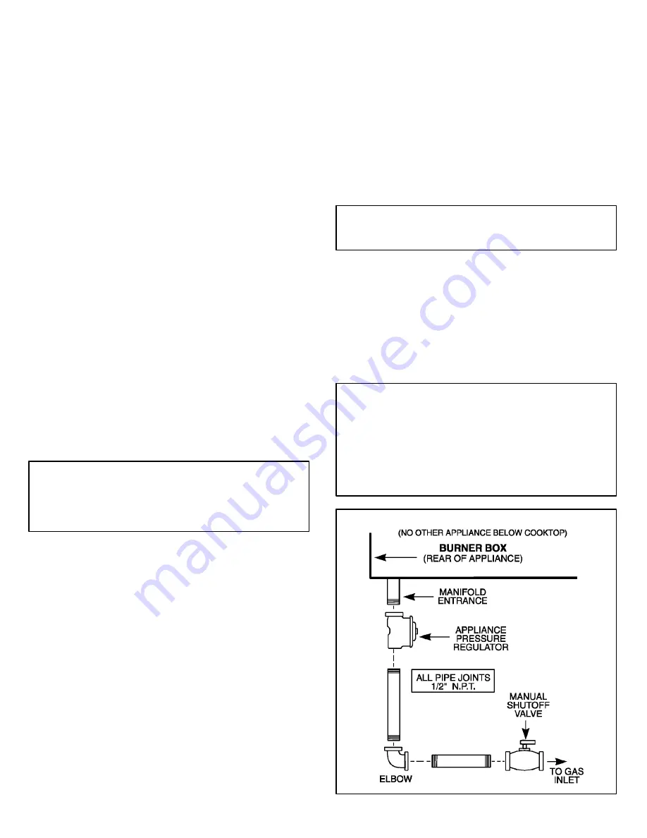
1. IF NO OTHER APPLIANCE IS TO BE INSTALLED BELOW THIS
COOKTOP
Join the appliance pressure regulator supplied with this appliance to the
entrance threads of the Gas Manifold. The appliance regulator is marked
with a directional arrow indicating correct direction of gas flow. Ensure the
appliance regulator is installed with the arrow pointing toward the gas
manifold entrance. Tighten the appliance regulator to 20 to 30 ft-lbs of
torque.
IMPORTANT
Never tighten to more than 35 ft-lbs of torque. Always use an approved
pipe joint compound resistant to the action of LP gas.
Install the appliance in its counter cutout.
Make the gas connection to the inlet of the appliance pressure regulator
with 1/2
²
male pipe threads.
Install a manual shut-off valve in an accessible location in the gas line
ahead of the appliance pressure regulator and external to this appliance for
the purpose of turning on or shutting off gas to the appliance.
Make additional pipe connections as necessary ahead of the shut-off valve
to the gas supply source. Assure all pipe joint connections are gas tight.
IMPORTANT
Apply a non-corrosive leak detection fluid to all joints and fittings in the
gas connection between the supply line shut-off valve and the range.
Include gas fittings and joints in the range if connections were disturbed
during installation. Check for leaks! Bubbles appearing around fittings
and connections will indicate a leak. If a leak appears, turn off supply line
gas shut-off valve, tighten connections, turn on the supply line gas shut
off valve, and retest for leaks. Never test for gas leaks with an open
flame.
FIGURE 3
ILLUSTRATIVE GAS SUPPLY PIPING