background image

7

CONVERTING APPLIANCE FOR USE

WITH LP GAS

WARNING

Propane conversion is to be performed by a JENN-AIR AUTHORIZED

SERVICER (or other qualified agency) in accordance with the

manufacturer’s instructions and all codes and requirements of the

authority having jurisdiction. Failure to follow instructions could result in

serious injury or property damage. The qualified agency performing this

work assumes responsibility for this conversion.

WARNING

Electrical power and gas must be turned off prior to

conversion.

This appliance was adjusted at the factory for use with natural gas. To

convert it for use with LP gas (propane or butane), each of the following

modifications must be performed:

A. Replace all orifice spuds

Step 1: Remove the grates and burner heads.
Step 2: Remove aluminum venturi tube.
Step 3: Trim a small piece of masking tape to the size of a dime and

affix it over the end of a 5/16

²

nut driver.

Step 4: Firmly press the nut driver over the orifice spud (figure 7) and

loosen spud by turning counterclockwise. Carefully lift nut

driver out of burner throat. Orifice spud should be captured in

the recess. Repeat this step for each burner.

FIGURE 7

REMOVAL OF ORIFICE SPUD

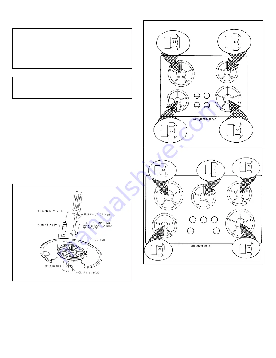
Step 5: Locate the LP orifice spud packet taped to the underside of the

burner box. The spuds have small numbers stamped on the

side. This number codes the orifice diameter and its correct

burner location. The following illustrations show correct LP

orifice spud location for 4 burner and 5 burner models,

respectively.

INSTALLATION OF LP ORIFICE SPUDS

FIGURE 8

4 BURNER MODEL (30

²

WIDE)

FIGURE 9

5 BURNER MODEL (36

²

WIDE)

Step 6: With the masking tape still in place in the recess of the nut

driver, press an LP orifice spud into the recess so that it is

snugly captured.

Step 7: Carefully install the orifice spud in the appropriate burner throat

by turning clockwise to tighten. Tighten to a torque of 15 to 20

inch-lbs.

Step 8: Replace cylindrical aluminum venturi tubes. Replace burner

heads and grates. Index each grate to its burner pan.

Step 9: Save the orifices removed from the appliance for future use.

Summary of Contents for CCG2423 Guide

Page 1: ...CUTOUT DIMENSIONS ARE CRITICAL 36 MODEL 30 MODEL INSTALLATION MANUAL SEALED GAS COOKTOPS CCG2423 AND CCG2523 JGC7430 AND JGC7536 SPECIALWARNING Improperinstallation adjustment alteration service main...

Page 2: ...d above cooking top Avoid use of cabinets above cooktop for storage space to eliminate associated potential hazards such as reaching over open flames PREPARATION OF COUNTERTOP The countertop cutout mu...

Page 3: ...oper pressure range S If this is a 36 wide model or if it is a 30 wide model and no other appliance is to be installed in the cabinetry below it proceed as instructed under paragraph I S If this is a...

Page 4: ...oin a manual shut off valve in an accessible location in the gas line ahead of the appliance regulator and external to the appliance for the purpose of turning on or shutting off gas to the appliance...

Page 5: ...thread Connection requires flare union adapters IMPORTANT Apply a non corrosive leak detection fluid to all joints and fittings in the gas connection between the supply line shut off valve and the ran...

Page 6: ...0XXXismountedbelowthisappliance andif thepower outlet for this appliance is to be located in the cross hatched area of figure 6 it is recommended the power cord be routed through the external vertical...

Page 7: ...driver over the orifice spud figure 7 and loosen spud by turning counterclockwise Carefully lift nut driver out of burner throat Orifice spud should be captured in the recess Repeat this step for eac...

Page 8: ...NNOT BE EASILY REMOVED TUCK THE FOLDS OF A CLOTH DISHTOWEL UNDER THEKNOB ANDPULL THETOWEL UPWARD WITH STEADY EVEN PRESSURE 3 Insert a slender thin blade screwdriver into the recess at center of valve...

Page 9: ...tallation of natural gas main spuds in their correct locations Save the orifices removed from the appliance for future use They will be needed if this appliance is again converted for use with LP gas...

Page 10: ...r are hazy and otherwise appear to have insufficient air obtain the services of a qualified service technician Specified input rates are as shown in figures 16 and 17 below FIGURE 16 4 BURNER MODEL BU...

Page 11: ...e caisson du br leur Ne pas tenter de convertir cet appareil en vue de l utilisation d un gaz autre que le type de gaz indiqu MOD LE DE 30 PO 30 po 76 2 cm 9 16 po 1 43 cm 21 po 53 34 cm Entr e du col...

Page 12: ...nstall es au dessus de la table de cuisson viter d utiliser les armoires situ es au dessus de la table de cuisson comme espace de rangement afin d liminer les dangers possibles par exemple lorsqu une...

Page 13: ...ns l armoire au dessous suivre les instructions de la section I S S il s agit d unappareil de30 pode largeuret qu unfour mural lectrique Jenn Air de mod le W30XXX ou W131 doit tre install dans l armoi...

Page 14: ...pareil et l ext rieur de la table de cuisson afin de pouvoir ouvrir ou couper l alimentation en gaz de l appareil Faire les raccords de tuyauterie additionnels requis la source d alimentation en gaz a...

Page 15: ...S CETTE TABLE DE CUISSON Coude filetage NPT de 1 2 po Adaptateur vas Raccord souple de l appareil max 5 pi Adaptateur vas R gulateur de pression de l appareil fourni respecter la direction d coulement...

Page 16: ...e W30XXX aussi pr s que possible du coin arri re gauche 3 Lorsquelemod leW30XXXest install souscet appareil et dans lecas o la prise de courant pour cet appareil doit tre install e dans la zone hachur...

Page 17: ...rne crous R p ter cette op ration pour chaque br leur FIGURE 7 ENL VEMENT DE LA T TE D INJECTEUR TUBE DE VENTURI EN ALUMINIUM SOCLE DU BR LEUR TOURNE CROUS DE 5 16 PO MORCEAU DE RUBAN CACHE COLL SUR L...

Page 18: ...L AIDE D UNE LAME DE M TAL SI ON NE PEUT PAS ENLEVER UN BOUTON FACILEMENT INS RER LES PLIS D UN CHIFFON VAISSELLE SOUS LE BOUTON ET TIRER VERS LE HAUT AVEC UNE PRESSION GALE ET FERME 3 Ins rer la lame...

Page 19: ...rver les t tes retir es de l appareil pour un usage ult rieur Ces t tes seront n cessaires si l appareil doit de nouveau tre converti l utilisation du gaz de p trole liqu fi B Retourner le capuchon du...

Page 20: ...u floues et semblent manquer d air communiquer avec un technicien de service comp tent Les figures 16 et 17 ci dessous donnent la puissance des divers br leurs FIGURE 16 MOD LE 4 BR LEURS EMPLACEMENT...

Reviews: