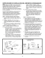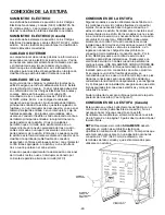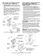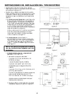
-11-
A QUALIFIED SERVICEMAN OR GAS APPLIANCE
INSTALLER MUST MAKE THE GAS SUPPLY
CONNECTION. Leak testing of the appliance shall be
conducted by the installer according to the instructions
given.
INSTALL GAS SHUTOFF VALVE
Install a manual shutoff valve in an accessible location in
the gas line external to this appliance for the purpose of
turning on or shutting off gas to the appliance.
Make the gas connection to the inlet of the pressure
regulator on this appliance with a 1/2
²
male pipe thread.
Use an approved pipe joint compound resistant to the
action of LP gas at pipe connections. Test all joints for
gas leaks with a soap and water solution or other
accepted leak detection means. Never test for gas leaks
with an open flame.
PRESSURE TESTING
The maximum gas supply pressure for the regulator
supplied on this appliance is 14
²
Water Column. The test
pressure for checking this regulator must be at least 6
²
Water Column for natural gas, and at least 11
²
Water
Column for LP. It is shipped from the factory set for
natural gas at 5
²
Water Column.
This appliance and its individual shutoff valve must be
disconnected from the gas supply piping system during
any pressure testing of that system at test pressures in
excess of 1/2 PSIG (3.5 k Pa).
This appliance must be isolated from the gas supply
piping system by closing its individual manual shutoff
valve during any pressure testing of the gas supply piping
system at test pressures equal to or less than 1/2 PSIG
(3.5 k Pa).
APPLIANCE PRESSURE REGULATOR
CONVERSION
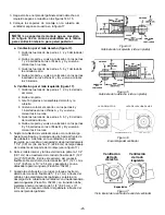
(See illustration “A”)
Follow the instructions below to convert the regulator for
use with LP gas. (This appliance is shipped from the
factory adjusted for use with natural gas.)
1. Unscrew the hex shaped cap from the neck of the
regulator. (A wrench may be required to loosen the
cap.)
2. Within the cap is a plastic pin. Remove this pin from
the cap by applying sideward pressure to the pin. (See
illustration.)
3. Invert the pin and snap it back into place within the cap
by applying even finger pressure at opposing edges of
the pin’s circular disc. The pin must be seated firmly
and squarely in the cap.
Pin replacement may be most easily accomplished by
placing the cap on a flat horizontal surface, as shown in
the illustration, and applying downward finger pressure
at the edges of the pin’s disc.
CONNECTING APPLIANCE TO GAS SUPPLY
MAXITROL REGULATOR
ILLUSTRATION “A”
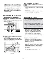
HARPER-WYMAN REGULATOR
ALTERNATE ILLUSTRATION “A”
The reversible cap is
labeled either “LP” or
“NAT” and is easily
recognized by the
raised center coin slot
(for Natural) or the
center well (for LP).
4. Screw the cap securely back into place in the neck of
the pressure regulator. (The cap need not be
wrench-tightened upon replacement. Firm finger
tightening will secure the cap.)
To convert regulator to LP insert a coin into the slot in the
cap of the regulator and turn counterclockwise to loosen.
Reverse (invert) cap, push down and turn clockwise to
lock in place. When finished, the marking “LP” should be
visible in the center well of the cap.
CONVERSION TO LP GAS
(See illustration “B”)
This appliance is shipped from the factory equipped for
use with natural gas. To convert it from natural gas for
use with LP gas, perform steps 1 through 4.
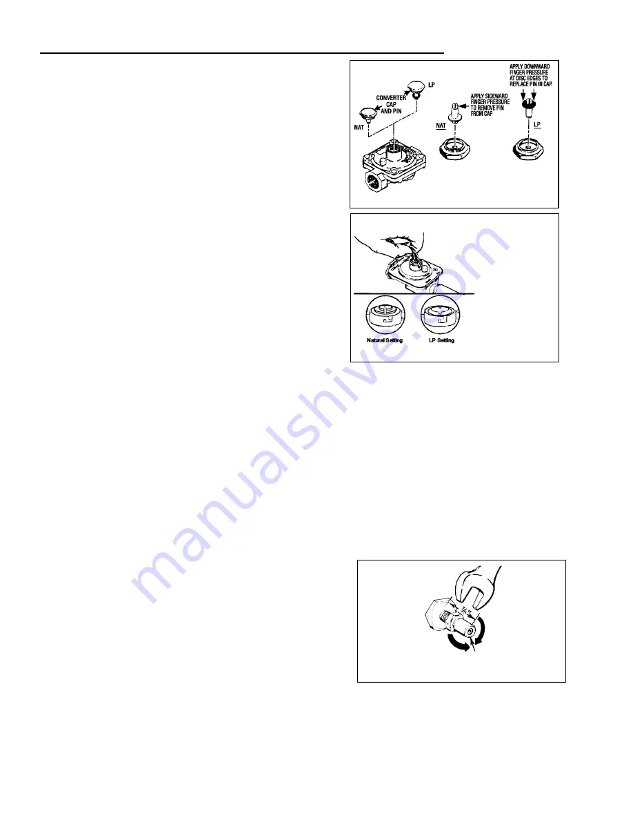
1/2
²
OPEN END
WRENCH
TURN
COUNTERCLOCKWISE
TO REMOVE
ORIFICE HOOD
TURN CLOCKWISE
TO TIGHTEN
ILLUSTRATION “B”
1. Remove natural gas orifice hoods. Remove LP orifice,
(if so equipped) in tube assemblies. Install color coded
orifice hoods supplied.
(SEE LP GAS CONVERSION
INSTRUCTIONS PAGE 15.)
2. Invert cap in convertible pressure regulator (if so
equipped) located at entrance to gas manifold.


