


©2004 Maytag Services
16023537
B–3
Use and Care
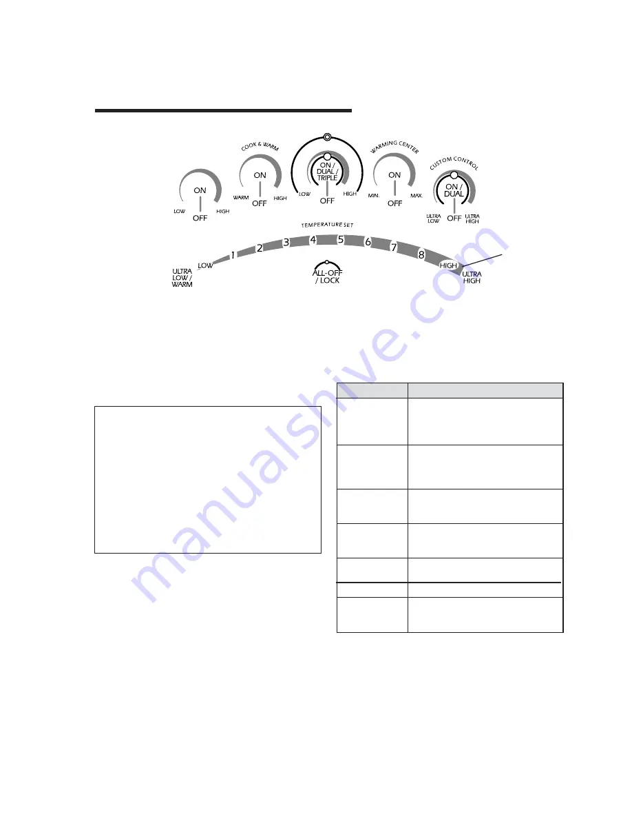
Using the Touch Control
• Press the desired
ON
pad. A light on the left side of the
control will blink.
• While the light is blinking, press the desired temperature
setting using the Temperature Selector Bar.
• A beep will sound each time a pad is pressed.
Setting the Controls
1. Place pan on surface element.
2. Press
ON
.
3. Select the temperature setting using the Temperature
Selector Bar.
4. When cooking is completed, press
OFF
and remove the
pan.
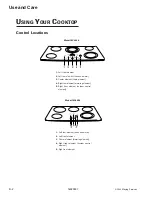
U
SING
Y
OUR
C
OOKTOP
Surface Controls
Suggested Heat Settings
The size, type of cookware and cooking operation will affect
the heat setting. For information on cookware and other
factors affecting heat settings, refer to “Cooking Made
Simple” booklet.
SETTINGS
USES
Ultra High
Offers higher speed cooking that can be
used to quickly bring water to a boil,
searing, blackening and for large-
quantity cooking.
High
Use to bring liquid to a boil. Always
reduce setting to a lower heat when
liquids begin to boil or foods begin to
cook.
6-8
Use to brown meat, heat oil for deep fat
(medium high)
frying or sauteing. Maintain fast boil for
large amounts of liquids.
4-6
Use to maintain slow boil for large
(medium)
amounts
of liquids and for most frying
operations.
2-4
Use to continue cooking covered foods
(medium low)
or steam foods.
Low
Use to melt butter or chocolate.
Ultra Low/
Offers a lower temperature for cooking
Warm
delicate sauces without scorching. Use
to keep cooked foods warm.
Notes
• If a temperature setting is not selected within approxi-
mately 10 seconds, the element will automatically shut
off.
• To change the temperature setting while cooking with
one element, press the
ON
pad and select a new
temperature on the Temperature Selector Bar while the
light is blinking.
• To change the temperature setting when multiple
elements are on, press the
ON
pad for the desired
element, then select a new temperature on the Tempera-
ture Selector Bar while the light is blinking.
Temperature
Selector Bar
Style varies
by model.


