background image

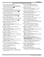
For Service Technician Use Only

DIAGNOSTICS 

2-4  

n


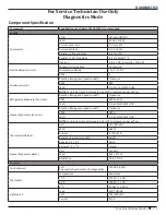
Four Door Bottom Mount

Ice & Water

Dual Water Valve

Watts

Green side 20 W 

Red side 35 W

Isolation Valve

Watts

20 W (Green)

Ice Box Fan

Rotation (facing end opposite shaft)

Clockwise

RPM

3500

Watt

4.2 W ± 15% @ 14 VDC

No-Load Performance, Controls in Normal Position

kW/24 hr/±0.4

Percent Run 

Time/±10%

Cycles/24 hr 

/± 10

Refrigerator 

Compartment 

Average Food 

Temperature  

± 4

°

F/-16

°

C

Freezer 

Compartment 

Average Food 

Temperature  

± 5

°

F/-15

°

C

Ice Maker 

Compartment 

Average Food 

Temperature  

± 5

°

F/-15

°

C

Ambient 

°

F/

°

C

70

°

F

90

°

F

110

°

F 70

°

F

90

°

F

110

°

F

70

°

F

90

°

F

110

°

F

70

°

F

90

°

F

110

°

F

70

°

F

90

°

F

110

°

F

70

°

F

90

°

F

110

°

F

21

°

C

32

°

C

43

°

C

21

°

C

32

°

C

43

°

C

21

°

C

32

°

C

43

°

C

21

°

C

32

°

C

43

°

C

21

°

C

32

°

C

43

°

C

21

°

C

32

°

C

43

°

C

29 Cu. Ft.

0.9

1.55

2.8

50%

70%

90%

28

22

10

37

°

F

37

°

F

37

°

F

0

°

F

0

°

F

0

°

F

24

°

F

24

°

F

24

°

F

2.8

°

C

2.8

°

C

2.8

°

C

-17.8

°

C

-17.8

°

C

-17.8

°

C -4.4

°

C

-4.4

°

C

-4.4

°

C

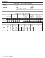
Temperature Relationship Test Chart

Refrigerator 

Evaporator Inlet/

Outlet ± 5

°

F/-15

°

C

Freezer Evaporator 

Inlet/Outlet  

± 5

°

F/-15

°

C

Suction Line 


± 7

°

F/-14

°

C

Average Total 

Wattage ± 10%

Suction Pressure 


± 2 PSIG 

Head Pressure  

± 5 PSIG 

Ambient 

°

F/

°

C

70

°

F

90

°

F

70

°

F

90

°

F

70

°

F

90

°

F

70

°

F

90

°

F

70

°

F

90

°

F

70

°

F

90

°

F

21

°

C

32

°

C

21

°

C

32

°

C

21

°

C

32

°

C

21

°

C

32

°

C

21

°

C

32

°

C

21

°

C

32

°

C

29 Cu. Ft.

15

°

F

20

°

F

-11

°

F

-8

°

F

80

°

F

104

°

F

80-100

80-100

6.0

3.6

70

125

-9.4

°

C

-6.7

°

C

-23.9

°

C

-22.2

°

C

26.7

°

C

40

°

C

Summary of Contents for JFX2897DRM

Page 1: ...RVICE MANUAL Four Door Bottom Mount W11390550 R 130 Model Nos JFX2897DRM JFX2897DRP MFX2876DRE MFX2876DRH MFX2876DRM WRF989SDAB WRX988SIBB WRX988SIBE WRX988SIBH WRX988SIBM WRX988SIBW Multimedia Enhanc...

Page 2: ...the Use and Care Guide or Installation Instructions provided with the refrigerator GOALS AND OBJECTIVES The goal of this Service Manual is to provide information that will enable the In Home Service P...

Page 3: ...12 SECTION 2 DIAGNOSTICS 2 1 SAFETY 2 2 DIAGNOSTICS MODE 2 3 CONTROL BOARD TROUBLESHOOTING 2 5 DIAGNOSTIC LOAD SERVICE TEST 2 6 SECTION 3 COMPONENT TESTING 3 1 SAFETY 3 2 WIRING DIAGRAM 3 3 SCHEMATIC...

Page 4: ...iv n Four Door Bottom Mount Notes...

Page 5: ...tion 1 General Information This section provides general safety parts and information for the Four Door Bottom Mount Refrigerator Safety Product Specifications Product Feature Control Panel Model Seri...

Page 6: ...rigerator follow these basic precautions Remove doors from your old refrigerator Use nonflammable cleaner Keep flammable materials and vapors such as gasoline away from refrigerator Use two or more pe...

Page 7: ...luding Doors IN inches 295 8 Depth With Door Open 90 Degree IN inches 481 2 Depth IN inches 351 2 Height to Top of Cabinet IN inches 683 4 Height to Top of Door Hinge IN inches 701 8 Height IN inches...

Page 8: ...d Drawers 3 Partial Width Non Climate Control Drawers No Temperature Controlled Drawers 1 External Refrigerated Drawer Door Bins 4 Adjustable Full Width Supplementary Containers No Lighting LED Liner...

Page 9: ...Top of Door Hinge IN inches 701 8 Height IN inches 701 8 Width IN inches 355 8 Description Type of Refrigerator French Door Details Advance Foam Insulation 99 9 lower Global Warming Potential and Bet...

Page 10: ...e Control Drawers 1 Partial Width Temperature Controlled Drawers 1 External Refrigerated Drawer Door Bins 1 Fixed 1 Liter 3 Adjustable Gallon Supplementary Containers EasySlide Bin Lighting LED Freeze...

Page 11: ...Type of Refrigerator French Door Details Advance Foam Insulation 99 9 lower Global Warming Potential and Better Energy Performance Exterior Base Grille Color Black or White or Grey Cabinet Color Blac...

Page 12: ...ezer Drawer Basket 1 Full Width Lower Plastic 1 Full Width Middle Plastic 1 Full Width Upper Plastic Door Bins Pizza Pocket Light LED Dispenser Dispenser Type Exterior Ice and Water Dispenser Options...

Page 13: ...oor Bottom Mount n 1 9 GENERAL INFORMATION Product Features CONTROL PANEL JennAir 69 Standard Depth French Door Refrigerator Maytag 36 Wide 4 Door French Door Refrigerator with Maytag Steel Shelves 26...

Page 14: ...1 10 n Four Door Bottom Mount GENERAL INFORMATION Whirlpool 36 Wide 4 Door Refrigerator with More Flexible Storage 26 cu ft...

Page 15: ...m Mount n 1 11 GENERAL INFORMATION Model Serial Number and Tech Sheet Location Model and Serial plate Open the Left door and look up to the front of the ceiling Tech sheet is located under the right s...

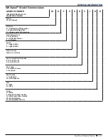
Page 16: ...Bottom Freezer Product Type X Double Drawer Pantry I W Y Double Drawer Freezer W External Water Canada Z Reversible Doors Capacity 28 26 cu ft Feature Pack 72 Flush Dispense Cap Touch Single Evap 76 F...

Page 17: ...ration U Undercounter Refrigeration Sub Platform Fuel F French Door X FD Double Drawer Z All Freezer Series 7 High GOLD 9 High GOLD Feature Level Feature Level 0 9 Key Feature Size Derivative 8 18 or...

Page 18: ...1 14 n Four Door Bottom Mount GENERAL INFORMATION Notes...

Page 19: ...r Bottom Mount n 2 1 Section 2 Diagnostics This section provides diagnostic mode and sales mode information for the Four Door Bottom Mount Safety Diagnostics Mode Control Board Trobleshooting Diagnost...

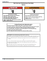
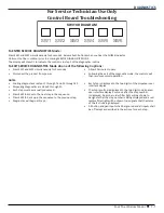
Page 20: ...istance away from the appliance to prevent potential injury Always use the proper testing equipment After voltage measurements always disconnect power before servicing IMPORTANT Electrostatic Discharg...

Page 21: ...Fan blade must be fully seated on shaft to achieve proper airflow Refrigerator Evaporator fan motor Rotation facing end opposite shaft Clockwise RPM 3300 10 Watt 2 8 15 W 14 VDC Freezer Evaporator fan...

Page 22: ...0 F 110 F 70 F 90 F 110 F 70 F 90 F 110 F 70 F 90 F 110 F 70 F 90 F 110 F 21 C 32 C 43 C 21 C 32 C 43 C 21 C 32 C 43 C 21 C 32 C 43 C 21 C 32 C 43 C 21 C 32 C 43 C 29 Cu Ft 0 9 1 55 2 8 50 70 90 28 22...

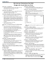
Page 23: ...NOTES Cooling diagnostics are steps 1 through 7 and 32 through 39 Dispensing diagnostics are steps 8 through 31 Each step must be manually advanced Press SW5 to move to the next step in the sequence P...

Page 24: ...tal open Service Test 7 Defrost Mode The defrost mode can be set by using SW3 In ADC mode the refrigerator will automatically defrost after a minimum of 8 hours of compressor run time up to a maximum...

Page 25: ...pass or Er Fail Service Test 34 Vertical Mullion Heater Mode Set the Vertical Mullion Heater Sensor Mode by selecting SW3 01 Sensor Operation On 02 Sensor Operation Off Heater on 100 Service Test 35...

Page 26: ...For Service Technician Use Only DIAGNOSTICS 2 8 n Four Door Bottom Mount Notes...

Page 27: ...Door Bottom Mount n 3 1 Section 3 Component Testing This section provides the schematic diagram wiring diagram and component location for the Four Door Bottom Mount Safety Wiring Diagram Schematic Dia...

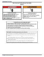
Page 28: ...e distance away from the appliance to prevent potential injury Always use the proper testing equipment After voltage measurements always disconnect power before servicing IMPORTANT Electrostatic Disch...

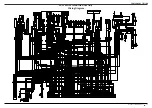
Page 29: ...SPLICE 3 SPLICE 2 SPLICE 9 SPLICE 1 SPLICE 8 SPLICE 7 SPLICE 6 SPLICE 5 SPLICE 10 SPLICE 11 TN TN TN RD GN YL GN YL RD BU BU WH WH RD WH WH PK PK BK BK YL YL BR BR WH RIP CORD WH RIP CORD 1 1 2 2 3 3...

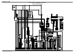
Page 30: ...WM Vcc Vcc RC EVAP FAN DC YL RD TN RD WH RD BK OR RC LED TOP 1 RC LED LEFT 1 RC LED LEFT 2 RC LED RIGHT 1 RC LED RIGHT 2 PANTRY LED 1 PANTRY LED 2 RC LED TOP 2 RC LED TOP 3 RC LED TOP 4 RC LED TOP 5 F...

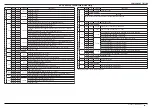
Page 31: ...VDC INVERTER OUTPUT 3 6 VDC WHEN COMPRESSOR IS RUNNING P9 P9 2 P9 3 12 VDC SHELF LIGHTING OUTPUT P12 P12 4 P1 2 115 VAC PANTRY HEATER OUTPUT SERVICE TEST 73 01 115 VAC P12 6 P1 2 ICE MAKER HEATER OUT...

Page 32: ...ce Technician Use Only COMPONENT TESTING 3 6 n Four Door Bottom Mount Component Location A B C D E F A Condenser Fan B Condenser C Freezer Evaporator D Ice Crusher Box E Front Door Dispenser Unit F Co...

Page 33: ...y Drawer Pantry Drawer User Interface Pantry Drawer Door Pantry Door Bar Pantry Cable and Pantry Thermistor Crisper Base Servicing Crisper Base Vertical Mullion Secondary Mullion Secondary Mullion LED...

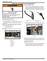
Page 34: ...s replaceable 4 Disconnect wire harness connector to coil Straighten the three metal tabs holding the coil on the valve and then lift off NOTE When replacing the magnetic coil position the coil on the...

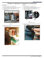
Page 35: ...machine compartment base 4 Unplug the wire harnesses Disconnect the water lines to remove the water valve Inverter 1 Unplug refrigerator or disconnect power 2 Access the inverter by removing screws ho...

Page 36: ...Pull the inverter away from the compressor to disconnect the green chassis ground wire and the compressor terminal block Compressor 6 Access the compressor terminal block as shown in below figure to m...

Page 37: ...t blade screwdriver Pull out bottom of fascia to disengage upper tabs NOTE If your ice box assembly has a revised ice box fascia with heater you will need to disconnect the fascia heater wiring harnes...

Page 38: ...en the two 9 Start from left to right slide your hand between the water reservoir cover and refrigerator compartment liner to disengage the snaps 10 Disengage rear left snap 11 Slide water reservoir c...

Page 39: ...isconnect dispenser and ice maker fill tubes 16 Drop the front of the housing and disengage the rear tabs from the three slots in the top of the refrigerator cabinet 17 Disconnect 1 4 6 4 mm reservoir...

Page 40: ...ts Continued 18 Lift dual water valve to remove 19 Press tab and lift up on filter switch cover to disengage the two tabs on opposite side to remove cover 20 To remove filter switch press release tab...

Page 41: ...es 4 Open the pentry drawer to its full extension Pantry Drawer User Interface 5 Starting from one of the sides put a flat head screwdriver into the slot and press to release the tab 6 Hold the releas...

Page 42: ...ove the pantry door Pantry Door Bar 12 Depress tabs using a straight blade screwdriver to remove the left and right side gear covers 13 Release the left side collar using a screwdriver 14 Lift out the...

Page 43: ...ssing Refrigerator Compartment Components Continued 17 Remove the tape securing the cable in the channel 18 Lift out the cable 19 Remove the pantry thermistor 20 Release the cable cover from the assem...

Page 44: ...Temperature Controlled Pantry Drawer instructions steps 1 21 2 Remove the foam piece on the front which pops up 3 At the front left side remove the harness cover using a flat blade screwdriver 4 Remo...

Page 45: ...e the screws 9 Release the left and right side retainers on the ends of the base assembly with the screwdriver 10 The wheels and heater can be serviced Vertical Mullion 11 Gently pry at sides to pop o...

Page 46: ...ment Components Continued Secondary Mullion 14 Press tabs to remove right side and left side harness cover Disconnect harness 15 Release the tabs under the mullion at the both end 16 Slide out the sec...

Page 47: ...Pull forward the center divider and lift out 21 To remove the rails on the divider remove the two screws holding the divider NOTE When removing rails on either sides of divider there is a screw that...

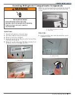
Page 48: ...6 2 Remove any remaining items and shelves in Refrigerator Compartment 3 Release 6 locking tabs there are two tabs at 3 locations along the center shelf rail 4 Drop down the air tower and remove RC Ev...

Page 49: ...C Evaporator Fan Motor 7 Disconnect wire harness 8 Separate the fan motor from the housing There are four rubber isolators that secure the motor to the housing Remove the fan motor RC Evaporator Therm...

Page 50: ...0 RC defrost thermistor clips on the evaporator coil and senses the coil temperature The defrost thermistor is part of the RC wiring harness To replace order the wiring harness Door Switch 1 To remove...

Page 51: ...e the shoulder screws from the door Upper Basket 1 Open the freezer drawer to its full extension 2 Release the retainers on the right and left sides of the basket 3 Lift out the upper basket by pressi...

Page 52: ...basket out Top Freezer Basket Adaptor 11 Pull out the rail and align the hole in slide with 1 4 6 4 mm screw in the rail 12 Remove the screw with the screwdriver 13 Pull out the assembly and remove th...

Page 53: ...ur 1 4 6 4 mm screws to remove FC evaporator cover to access FC evaporator and evaporator components 5 Remove two screws to remove the fan assembly When installing fan make sure foam gaskets are in pl...

Page 54: ...d the hinge Ice Box Assembly 1 Complete the steps 1 11 from Refrigerator Compartment Components instructions 2 Disconnect electrical connections to ice box assembly 3 Disconnect ice maker fill tube fr...

Page 55: ...on ice box assembly NOTE Some models have an ice box fascia with fascia heater wired through the foil fill tube heater you may need to remove the fascia heater wires and grommet from the ice box cove...

Page 56: ...ssing Ice Maker and Dispenser Components Continued Ice Maker and Fan Motor 10 Remove foam block 11 Lift out ice maker and disconnect the wire harness 12 Lift out the fan motor and disconnect the wire...

Page 57: ...remove user interface UI assembly 2 Pull out and lower UI then disconnect board from wire harness connectors to remove 3 To remove ice door assembly remove the two screws securing assembly to refriger...

Page 58: ...COMPONENT ACCESS 4 26 n Four Door Bottom Mount Notes...

Page 59: ...MBER READY TO IDENTIFY YOU AS AN AUTHORIZED IN HOME SERVICE PROFESSIONAL FOR LITERATURE ORDERS CUSTOMER EXPERIENCE CENTER PHONE 1 800 851 4605 FOR TECHNICAL INFORMATION AND SERVICE POINTERS www servic...

Page 60: ......

Reviews: