3
INSTALLATION REQUIREMENTS
Tools and Parts
Gather the required tools and parts before starting installation.
Read and follow the instructions provided with any tools
listed here.
Tools Needed
■
Tape measure
■
Marker or pencil
■
Phillips screwdriver
■
Pliers
■
Flat-blade screwdriver
■
Jigsaw
■
Level
■
Caulking
■
Drill
■
Aluminum duct tape
■
T20
®†
TORX
®†
drivers
Parts Supplied
Check that all parts are included.
■
Cooktop assembly
■
Blower housing assembly with electronic box assemblies
■
(4) Cooktop mounting brackets (corners)
■
Grease filter
■
(11) M4 x 9.5 mm screws (ducting and electrical box
strain reliefs)
■
(16) M4 x 12 mm screws (cooktop mounting brackets
to cabinet)
■
(4) M6 x 16 mm screws (blower motor assembly to
cabinet floor)
■
(4) M5 x 10 mm flat-head screws (mounting feet to
blower motor assembly bottom)
■
(4) M5 x 50 mm cap head screws (cooktop-to-cooktop
mounting brackets)
■
(4) M5 lock washers
■
(4) M5 flat washers
■
(2) UL listed or CSA approved
M\,
" (2.2 cm) strain relief
■
Rectangular duct 2-piece telescoping (blower assembly
to cooktop)
■
Foam strip
Parts Needed
■
A UL listed or CSA approved strain relief for
M\,
" (2.2 cm)
knockout
■
(4) UL listed wire connectors for 8-gauge wires
For vented installations:
■
3
Z\v
" x 10" (8.3 cm x 25.4 cm) metal ducting
■
Jenn-Air
®
wall cap:
Jenn-Air
®
3¼" x 10" (8.3 cm x 25.4 cm) Surface Wall Cap
Damper part number A403.
See the “Assistance or Service” section in your Use and
Care manual to order.
For non-vented installations:
■
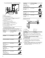
Recirculation Kit part number W10807915 (See the
“Assistance or Service” section in your Use and Care
manual to order.)
a.
Recirculation duct housing
b.
(4) Mounting screws
c.
(2) Charcoal filters
d.
Recirculation housing cover
e.
(2) Mounting screws – cover
f.
Duct extension
g.
(4) Mounting screws – duct extension
For non-vented installations side recirculation only:
■
3
Z\v
" x 10" (8.3 cm x 25.4 cm) metal duct – length required
is determined by the distance from the exhaust outlet to the
back flat surface of the Recirculation Kit housing.
Check local codes. Check existing electrical supply. See the
“Electrical Requirements” section.
It is recommended that all electrical connections be made by
a licensed, qualified electrical installer.
Location Requirements
IMPORTANT:
Observe all governing codes and ordinances.
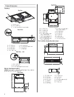
When installing the cooktop, use the minimum dimensions given.
■
To eliminate the risk of burns or fire by reaching over the
heated surface units, cabinet storage space located above
the surface units should be avoided. If cabinet storage is to
be provided, the risk can be reduced by installing a range
hood that projects horizontally a minimum of 5" (12.7 cm)
beyond the bottom of the cabinets.
■
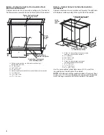
Use the countertop opening dimensions that are given
with these Installation Instructions. Given dimensions are
minimum clearances and provide 0" (0 cm) clearance.
■
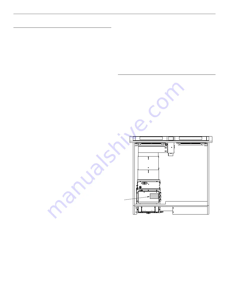
The model/serial/rating label is located on the front face of
the electrical junction box cover.
■
Grounded electrical supply is required. See the “Electrical
Requirements” section.
■
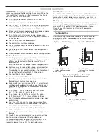
If cabinet has drawers, drawers will need to be removed
and drawer fronts installed on front of cabinet.
NOTE:
The exhaust system is for outside venting. For
non-vented (recirculating) installation, see “For non-vented
(recirculating) installations only” in the “Connect Vent System”
section. Recirculating Kit part number W10807915 is available
from your dealer or an authorized parts distributor.
IMPORTANT:
An undercounter built-in oven cannot be installed
under this product.
A
A. Model/serial/rating label location
†
®TORX and T20 are registered trademarks of Acument Intellectual Properties, LLC.


