background image

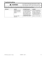
Troubleshooting

To avoid risk electrical shock, personal injury, or death,
always disconnect electrical power source to the freezer
before attempting to service, unless test procedures require

power to be connected. When removing any wiring from terminals they must be replaced on the same terminals.
Ensure all ground wires are connected before certifying unit as repaired and/or operational.

WARNING

!

©2003 Maytag Appliances Company

16022323   Rev. 0

9

PROBLEM


CHECK


POSSIBLE CAUSE


REMEDY


Interior too cold or 
contents freezing. 

Thermostat setting 

Thermostat set to too cold 
of a setting for ambient 
conditions. 

Adjust thermostat warmer 
setting (lower number on 
knob). 


The evaporator for the 
presence of a uniform 
frost pattern. Is the frost 
confined to left wing and 
the left side of the back? 

Note:

 Compressor should 

be operating for least 5 
minutes with door open to 
perform this check. 

Refrigerant leak or low 
refrigerant charge in the 
sealed system. 
Refrigerant volume in 
evaporator is not sufficient 
to cool the region of the 
plate where the 
evaporator plate sensing 
thermostat’s thermo bulb 
mounts. Therefore the 
control thermostat never 
reaches its cutout 
temperature and the 
compressor operates 
100% of the time. The 
remaining evaporator 
volume is sufficient to cool 
the air temperature below 
freezing. 

Locate and correct cause 
of refrigerant leak. 
Replace drier, evacuate 
and recharge sealed 
refrigerant system with the 
proper amount of charge 
as listed on the unit’s data 
plate. 

 Thermostat 

(compressor 

control) thermo bulb 
mounting or routing. 

Mounting location 
incorrect. Model should be 
on the right wing of the 
evaporator plate. All other 
models mount at the rear 
top center of the 
evaporator. 

Relocate thermo bulb to 
proper location. 


Thermostat sensing tube 
(capillary tube) resting on 
or above compressor 
dome in mechanical 
compartment causing 
false sensing. 

Reroute sensing tube 
clear of compressor dome 
area. 


Thermostat thermo bulb 
mounting bracket not 
secure, causing false 
sensing. 

Securely tighten thermo 
bulb mounting bracket. 

  Insufficient 

thermo 

bulb 

contact area on 
evaporator U-shaped loop 
with 3-inch long legs 
required. Bracket should 
be located at mid point of 
each 3-inch leg. Both legs 
secured under bracket. 

Adjust thermo bulb contact 
area to achieve sufficient 
contact. A U-shaped loop 
with 3-inch long legs is 
required. The mounting 
bracket should be located 
at the mid-point of each 3-
inch leg.  Both legs 
secured under bracket. 


Summary of Contents for JUC2450ACX

Page 1: ...es but is not limited to the following Jenn Air JWC2450ARB JWC2450ARW JWC2450ARS JWC2450ACX JUC2450ARB JUC2450ARW JUC2450ARS JUC2450ACX Service This manual is to be used by qualified appliance technic...

Page 2: ...NING REPAIRS WARNING To avoid risk of severe personal injury or death disconnect power before working servicing on appliance to avoid electrical shock To locate an authorized servicer please consult y...

Page 3: ...Drier 7 Evaporator 8 Thermistor 8 Troubleshooting 9 13 Disassembly Procedures Replacing the Evaporator 14 Compressor Removal 14 Compressor Installation 14 Condenser Removal 15 Condenser Installation...

Page 4: ...ed otherwise For positive identifications of individual units state complete serial number model and type This information is found on the serial plate located on front upper right hand corner of food...

Page 5: ...t electrical power source to unit unless test procedures require power to be connected Discharge capacitor through a resistor before attempting to service Ensure all ground wires are connected before...

Page 6: ...source to unit unless test procedures require power to be connected Discharge capacitor through a resistor before attempting to service Ensure all ground wires are connected before certifying unit as...

Page 7: ...t power to refrigerator 2 Discharge capacitor if present by shorting terminals through a resistor 3 Remove compressor leads and use an ohmmeter set on highest scale 4 Touch one lead to compressor body...

Page 8: ...t electrical power source to unit unless test procedures require power to be connected Discharge capacitor through a resistor before attempting to service Ensure all ground wires are connected before...

Page 9: ...scharged gas is at a higher temperature than air that is passing over condenser It is very important that adequate air flow over condenser is maintained Condenser is air cooled by condenser fan motor...

Page 10: ...s 2 and 3 are connected within relay Run capacitor is connected to relay terminal 3 L2 side of 120 VAC power is connected to relay terminal 2 1 Disconnect power to the refrigerator 2 Remove relay cove...

Page 11: ...If refrigerator is under warranty old drier must accompany warranty claim Component Description Test Procedures Evaporator Inner volume of evaporator allows liquid refrigerant discharged from capilla...

Page 12: ...Ensure all ground wires are connected before certifying unit as repaired and or operational 12 16022323 Rev 0 2003 Maytag Appliances Company Thermistor Temperature sensing bulb changes resistance wit...

Page 13: ...thermostat never reaches its cutout temperature and the compressor operates 100 of the time The remaining evaporator volume is sufficient to cool the air temperature below freezing Locate and correct...

Page 14: ...f the cabinet interior Interior too warm compressor operates Thermostat Thermostat set to too low warm of a setting Adjust thermostat to a colder setting higher number on knob Thermostat failed cuttin...

Page 15: ...connections Wiring connection to and from fan motor terminal block and thermostat loose or incorrect Correct loose or incorrect wiring connections Condenser fan motor failed Replace condenser fan ass...

Page 16: ...thermostat to terminal block loose or incorrect Correct loose or incorrect wiring connections Compressor runs fan does not run Fan motor and blade assembly Fan blade jammed by shroud refrigerant line...

Page 17: ...tional WARNING 2003 Maytag Appliances Company 16022323 Rev 0 13 PROBLEM CHECK POSSIBLE CAUSE REMEDY Position of door light activation over ride switch Is it in the on position If over ride switch is i...

Page 18: ...ss insulation tube are installed and sealed Also check the thermistor to make sure it has full contact and is secure Be sure to check for leaks and evacuate to 50 microns Compressor Removal 1 Disconne...

Page 19: ...emoval procedure Be sure to evacuate to 50 microns before weight charging If contamination was found or determined the evaporator should also be replaced at this time Condenser Fan Removal 1 Disconnec...

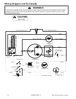
Page 20: ...atic 16 16022323 Rev 0 2003 Maytag Appliances Company WHITE OPTIONAL FEATURE FAN CONDENSER RELAY P T C RED RED LIGHT SWITCH BLACK SWITCH ON OFF BLUE BLACK RED BLUE TRANSFORMER INTERIOR FAN BLACK 4 8 2...

Page 21: ...2003 Maytag Appliances Company 16022323 Rev 0 A 1 Appendix A...

Page 22: ...O N T E N T S Introduction 1 Safety 2 Installation 3 11 Operation 12 Features 13 Care and Cleaning 14 Before Calling for Service 15 Warranty 17 Guide du propri taire 18 Gu a del Propietario 35 OWNER S...

Page 23: ...our future assistance with your wine chiller a complete model and serial number recorded in the spaces below will be extremely helpful These numbers are found on a data plate inside the wine chiller...

Page 24: ...your wine chiller should not be operated in the presence of gasoline or other flammable vapors and liquids To prevent injury children should not climb hang or stand on this wine chiller IMPORTANT Chi...

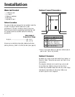
Page 25: ...ight Best performance will be maintained when installed within the following parameters Ideal Ambient Temperature Range Built In 65 80 F 18 27 C Provisions for electricity should be determined before...

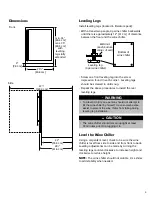
Page 26: ...nug Repeat the above procedures to install the rear leveling legs The wine chiller should remain upright at least 30 minutes prior to plugging it in CAUTION Level the Wine Chiller Using a carpenter s...

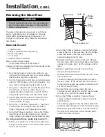
Page 27: ...el skip to step 12 7 Pull the door gasket out of the door s back frame enough to allow access to the screw holes and the back of the door lock 8 Using the Phillips screwdriver remove the Phillips scre...

Page 28: ...a smooth surface Align the glass door directly over the stainless steel frame overlay so that the lock extension will go through the hole in the glass door that is on the opposite end of where the loc...

Page 29: ...thickness at the screw locations 5 Use the following pilot hole drill sizes for the frame material Type of Pilot Hole Drill Size for Wood 8 Pan Head Wood Screws Hardwood 3 32 0 24 cm Softwood 5 64 0 2...

Page 30: ...ood is positioned on door Mounting surface non face side Mounting surface non face side Pre drilled pilot holes 10 places do not drill through wood frame Back side of door Back view Pre drilled pilot...

Page 31: ...e wine chiller remove it by unscrewing the top Allen head set screw at the top hinge Remove the door by angling the door off of the bottom hinge pin Wood frame Door hinge Shoulder bushing Washer Washe...

Page 32: ...aded section Make sure that the lock s key slot is vertical then tighten the 15 mm nut with a 15 mm deep well socket Magnetic door gasket Rear of door Light door striker plate Bottom of door 1 8 Allen...

Page 33: ...wine cooler at it s proposed location will allow the door to open sufficiently so that the wine racks can be pulled out if desired As a possible solution reversing the door swing may provide enough d...

Page 34: ...the door from closing OFF 7 6 5 4 3 2 1 C O L D E R Front bottles necks facing rear Rear bottles necks facing front Loading Tips and Suggestions 1 As with most refrigeration products there is a sligh...

Page 35: ...when the door is open Remember to turn off the light when it is no longer needed Pull out Racks The middle four racks may be pulled out approximately 6 15 cm to facilitate adding or removing bottles...

Page 36: ...oor Use a glass cleaner or mild detergent and water and soft cloth to clean the glass door Do not use abrasive powders Door Gasket The vinyl gasket may be cleaned with mild detergent and water or a so...

Page 37: ...reaker open Appliance runs long Prolonged door openings Control set too cold Condenser needs cleaning Moisture collects inside Too many door openings Hot humid weather increases condensation Moisture...

Page 38: ...16 Notes...

Page 39: ...ag ServicesSM Attn Jenn Air CAIR Center P O Box 2370 Cleveland TN 37320 2370 U S A and Canada 1 800 JENNAIR 1 800 536 6247 U S A customers using TTY for deaf hearing impaired or speech impaired 1 800...

Page 40: ...2003 Maytag Appliances Company 16022323 Rev 0 B 1 Appendix B...

Page 41: ...TA B L E O F C O N T E N T S Introduction 1 Safety 2 Installation 3 7 Operation 8 Features 8 Care and Cleaning 9 Before Calling for Service 10 Warranty 11 Guide de l utilisateur 12 Gu a del Usuario 2...

Page 42: ...sistance with your refrigerator a complete model and serial number recorded in the spaces below will be extremely helpful These numbers are found on a data plate located on the upper left side inside...

Page 43: ...uld not be operated in the presence of gasoline or other flammable vapors and liquids To prevent injury children should not climb hang or stand on this refrigerator This appliance is equipped with a t...

Page 44: ...l Ambient Temperature Range Built In 65 80 F 18 3 26 7 C Provisions for electricity should be determined before placing the refrigerator in its final location see page 2 If door is recessed between ca...

Page 45: ...epeat the above procedures to install the rear leveling legs The refrigerator should remain upright at least 30 minutes prior to plugging it in CAUTION Level the Refrigerator Using a carpenter s level...

Page 46: ...careful not to run the knife through the hinge found on each screw cover To avoid electrical shock which can cause severe personal injury or death disconnect power to the refrigerator before reversing...

Page 47: ...frigerator door 4 Reinstall the door by locating it over the bottom hinge pin and pushing down and in Reinstall the top hinge pin Check the door for proper alignment The top and sides of the door shou...

Page 48: ...into the pilot holes in the custom wood panel and tighten 6 Reinstall the door seal by pressing it into the door channel making certain the corners are fully inserted 7 Install the door back on the re...

Page 49: ...ooling but does not shut off power to the refrigerator To disconnect power the refrigerator must be unplugged or the circuit breaker or fuse board turned off OFF 7 6 5 4 3 2 1 C O L D E R To prevent i...

Page 50: ...Wash interior compartment with mild detergent and water Do not use an abrasive powder solvent polish cleaner or undiluted detergent Door Gasket The vinyl gasket may be cleaned with mild detergent and...

Page 51: ...r needs cleaning Noisy operation Refrigerator not level Weak floor Refrigerator cabinet Refrigerator not level vibrates Weak floor Refrigerator light Bulb burned out not working No power at outlet App...

Page 52: ...ag ServicesSM Attn Jenn Air CAIR Center P O Box 2370 Cleveland TN 37320 2370 U S A and Canada 1 800 JENNAIR 1 800 536 6247 U S A customers using TTY for deaf hearing impaired or speech impaired 1 800...

Reviews: