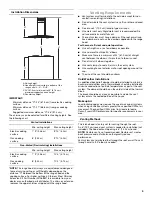
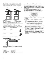
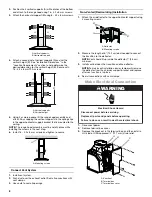
background image

9

4.

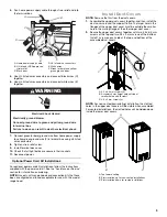
Run home power supply cable through strain relief and into 
the terminal box.

5.

Use UL listed wire connectors and connect black wires (C) 
together.

6.

Use UL listed wire connectors and connect white wires (E) 
together.

7.

Connect green (or bare) ground wire from home power supply 
to yellow-green ground wire (F) in terminal box using UL listed 
wire connectors.

8.

Tighten strain relief screw.

9.

Install terminal box cover.

10.

Check that all light bulbs are secure in their sockets.

11.

Reconnect power.

Optional Power Cord Kit Installations

For optional power cord kit installations, follow the instructions 
supplied with the power cord kit. See the “Assistance or Service” 
section for information on ordering.

NOTE:

 Use only with range hood cord connection kits that have 

been investigated and found acceptable for use with this model 
range hood.

Install Duct Covers

NOTE: 

Remove the film from the duct covers.

1.

Assemble the upper duct covers together, and then install the 
duct covers around the support frame. The larger hole in the 
flanges of the upper duct cover must be outside the smaller 
hole in the mating flange of the other upper duct cover.

2.

Secure the upper duct covers together with two 3.5 x 6.5 mm 
screws at the top and two 2.9 x 3 mm screws at the bottom. 
Install 1 screw on each side at the top and bottom of the 
assembled duct covers.

NOTE: 

For non-vented (recirculating) installation, the slotted 

holes in the upper duct covers will be visible when assembled. 
For vented installations, the slotted holes will be hidden down 
inside the lower duct covers.

A. Home power supply cable
B. UL listed or CSA approved 

strain relief

C. Black wires

D. UL listed wire connectors

E. White wires

F. Green (or bare) and yellow-

green ground wires

A

B

C

D

E

F

WARNING

Electrical Shock Hazard

Electrically ground blower.

Connect ground wire to green and yellow ground wire 
in terminal box.

Failure to do so can result in death or electrical shock.

A. 3.5 x 6.5 mm screws (2)
B. Assembly holes (larger hole outside of 

smaller hole on both sides)

C. 2.9 x 3 mm screws (2)

A. Top toward ceiling
B. Slots installed up for non-vented installations

C. Slots installed down for vented installations

A

A

B

C

C

A

B

C

Summary of Contents for JXI8536DS0

Page 1: ...nnair com In Canada call 1 800 JENNAIR 1 800 536 6247 or visit our website at www jennair ca Instructions d installation et Guide d utilisation et d entretien Au Canada pour assistance installation ou...

Page 2: ...OTTE 28 Nettoyage 28 SCH MA DE C BLAGE 29 ASSISTANCE OU SERVICE 30 Au Canada 30 Accessoires 30 GARANTIE 31 RANGE HOOD SAFETY You can be killed or seriously injured if you don t immediately You can be...

Page 3: ...3 IMPORTANT SAFETY INSTRUCTIONS READ AND SAVE THESE INSTRUCTIONS...

Page 4: ...ial rating plate The model serial rating plate is located behind the left filter on the rear wall of the vent hood Canopy hood location should be away from strong draft areas such as windows doors and...

Page 5: ...to seal exterior wall or roof opening around the cap The size of the vent should be uniform Cold Weather Installations An additional back draft damper should be installed to minimize backward cold air...

Page 6: ...k Quincy MA 02169 7471 CSA International 8501 East Pleasant Valley Road Cleveland OH 44131 5575 A 120 volt 60 Hz AC only 15 amp fused electrical circuit is required If the house has aluminum wiring fo...

Page 7: ...power supply cable and drill a 1 3 cm diameter hole for wire access 2 Run wire through the home power supply cable according to the National Electrical Code or CSA Standards and local codes and ordin...

Page 8: ...ulk to seal all openings Non Vented Recirculating Installation 1 Attach the air deflector to the upper horizontal support using 4 mounting screws 2 Measure the length of 6 15 2 cm duct needed to conne...

Page 9: ...port frame The larger hole in the flanges of the upper duct cover must be outside the smaller hole in the mating flange of the other upper duct cover 2 Secure the upper duct covers together with two 3...

Page 10: ...ced over the plastic clip to secure the lower duct covers together at the bottom 7 Secure the lower duct covers together at the top using plastic clips 2 Use one plastic clip on each side 8 Secure the...

Page 11: ...tween the gas cooktop and electric cooktop modes The Auto button light will flash 5 times when the range hood is changed to the electric cooktop mode Auto Sense is now set to work with electric cookto...

Page 12: ...ing Method Liquid detergent soap and water or all purpose cleanser Wipe with damp soft cloth or nonabrasive sponge and then rinse with clean water and wipe dry Metal Grease Filter 1 Open the stainless...

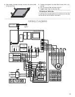
Page 13: ...fications Power Supply Frequency Power Absorbtion 120 VAC 60 HZ 420 W Motor Resistance Blue Black Blue Grey Blue Red Blue White 9 8 14 3 18 21 6 SE130B RD M 3 2 1 4 5 6 7 8 9 BU YL GN BR YL WH RD GY B...

Page 14: ...h any questions or concerns at Jenn Air Brand Home Appliances Customer eXperience Center 553 Benson Road Benton Harbor MI 49022 2692 Please include a daytime phone number in your correspondence In Can...

Page 15: ...rs preservation solutions etc 5 Defects or damage caused by the use of non genuine Jenn Air parts or accessories 6 Conversion of products from natural gas or L P gas 7 Damage from accident misuse abus...

Page 16: ...W10674115D 2015 Jenn Air Used under license in Canada All rights reserved Utilis sous licence au Canada Tous droits r serv s 3 15 Printed in Mexico Imprim au Mexique...

Reviews: