background image

GENERAL INFORMATION (CONT.)

JennAir® and KitchenAid® 36", 42", and 48" Built-In Side by Side Refrigerators 

n

 1-

9

Using The Controls

IMPORTANT:

n

The refrigerator control adjusts the refrigerator compartment

temperature. The freezer control adjusts the freezer

compartment temperature.

n

Wait 24 hours after you turn on the refrigerator before you

put food into it. If you add food before the refrigerator has

cooled completely, your food may spoil.

NOTE: 

Adjusting the refrigerator and freezer controls to a

lower (colder) setting will not cool the compartments any

faster.

n

If the temperature is too warm or too cold in the refrigerator

or freezer, first check the air vents to be sure they are not

blocked before adjusting the controls.

n

The preset settings should be correct for normal household

usage. The controls are set correctly when milk or juice is as

cold as you like and when ice cream is firm.

n

The actual temperature may differ from the display when a

door is open for an extended period of time.

NOTE:

 The factory recommended set points are 0°F (-18°C) for 

the freezer and 37°F (3°C) for the refrigerator.

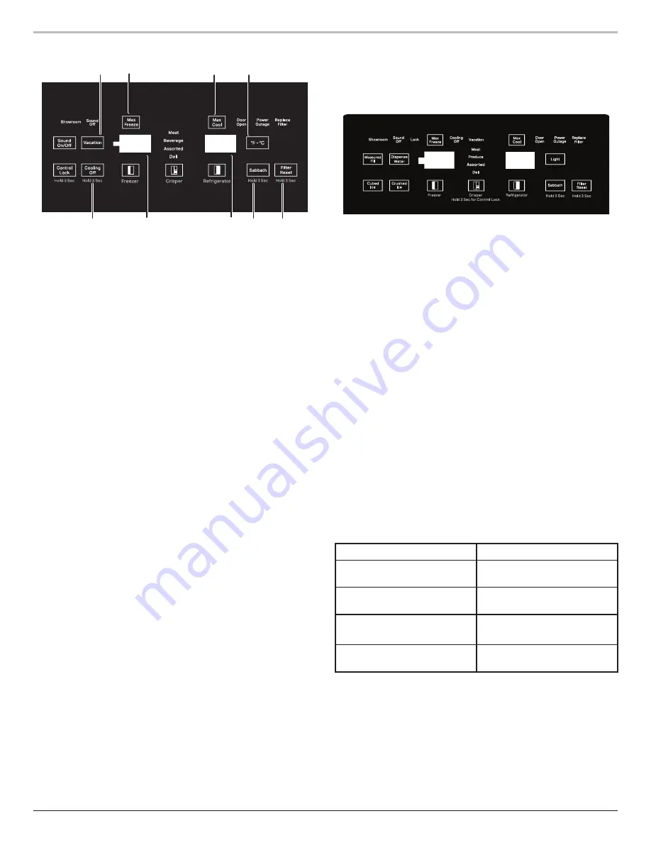
1. Turning Refrigerator ON and Viewing

Set Points

Your refrigerator and freezer will not cool when cooling is turned 

OFF. Follow the directions specific to your model.

Turn ON - Dispenser Model

n

Press and hold Max Freeze and Max Cool buttons at the same

time for 3 seconds.

n

Cooling OFF button blinks twice and remains ON.

Turn ON - Non-Dispensing Model

n

Press and hold Cooling OFF button for 3 seconds.

n

Cooling OFF button blinks twice and remains ON.

NOTE:

 The Cooling ON/OFF touch pad on the control panel shuts 

down refrigerator functions such as cooling, lighting, fans, and 

compressors. To turn the power OFF completely, use the power 

ON/OFF switch located behind the top grille.

2. Setting the Temperature F°/C°

Dispensing Models

Press and hold the Max Cool and Crisper buttons at the same 

time for 3 seconds to change between Celsius and Fahrenheit. 

When activated, the selected temperature option displays. When 

deactivated, the display is OFF.

Non-Dispensing Models

Press F°-C° button to change between Celsius and Fahrenheit. 

When activated, the selected temperature option displays. When 

deactivated, the LED is OFF.

3. Adjusting Controls

NOTE:

 Wait at least 24 hours between adjustments. Recheck the 

temperatures before other adjustments are made.

To Adjust Set Point Temperatures:

n

Press the refrigerator or freezer PLUS (+) or MINUS (-) touch

pad until the desired temperature is reached.

n

Press the Set to Recommended touch pad to reset the set

points to the factory recommended temperatures.

NOTE:

 The set point range for the freezer is -

8

°F (-2

2

°C) to 

5

°F (-1

5

°C). The set point range for the refrigerator is 3

3

°F


(

1

°C ) to 43°F (6°C).

Condition/Reason

Temperature Adjustment

REFRIGERATOR too cold

REFRIGERATOR Control 

1°C 

or 2°F


higher

REFRIGERATOR too warm

REFRIGERATOR Control 

1°C 

or 2°F


lower

FREEZER too cold

FREEZER Control 

1°C or 2°F


higher

FREEZER too warm/too little 

ice

FREEZER Control 

1°C or 2°F


lower

4. Water Filter Indicator and Reset

The water filter indicator, located on the control panel, will help 

you know when to change the water filter.

It is recommended that you replace the filter when “Replace 

Filter” is displayed or when water flow to your water dispenser 

and/or ice maker decreases noticeably.

After changing the water filter, press and hold FILTER RESET for 3 

seconds until the “Replace Filter” indicator light disappears.

1

7

5

5

2

3

3

6

4

Non-Dispenser Control Panel

Dispenser Control Panel

Summary of Contents for KitchenAid KBSD708M S00 Series

Page 1: ...MANUAL JennAir and KitchenAid 36 42 and 48 Built In Side by Side Refrigerators W11636548 Rev A JBSFS42NMX00 JBSFS48NMX00 JBSS42E22L00 JBSS48E22L00 KBSD702M S00 KBSD706MPS00 KBSD708M S00 KBSN702M 00 KB...

Page 2: ...ion on the model being serviced refer to the literature provided with the refrigerator GOALS AND OBJECTIVES The goal of this Technical Manual is to provide information that will enable the In Home Ser...

Page 3: ...1 SAFETY 1 2 PRODUCT SPECIFICATIONS 1 3 PRODUCT FEATURES 1 8 MODEL NUMBER NOMENCLATURE 1 14 MODEL NUMBER AND SERIAL NUMBER LABEL LOCATION 1 16 TECH SHEET LOCATION 1 16 SECTION 4 COMPONENT ACCESS 4 1 T...

Page 4: ...iv n JennAir and KitchenAid 36 42 and 48 Built In Side by Side Refrigerators Notes...

Page 5: ...ral Information This section provides general safety parts and information for the JennAir and KitchenAid 36 42 and 48 Built In Side by Side Refrigerators Safety Product Specifications Product Feature...

Page 6: ...nded by the manufacturer e g parts made at home using a 3D printer Keep ventilation openings in the appliance enclosure or in the built in structure clear of obstruction Do not use mechanical devices...

Page 7: ...h Closed Excluding Handles IN inches 24 or 25 Depth Closed Including Handles IN inches 27 16 Depth Excluding Doors IN inches 22 8 Depth With Door Open 90 Degree IN inches 46 4 or 47 16 or 50 4 or 50 1...

Page 8: ...ed Drawers 1 Full Width Freezer Compartment Door Type Swing Freezer Drawer Basket 2 Full Width Lower Freezer Number of Shelves 4 or 6 Freezer Type Standard Light LED Shelves 2 Adjustable Full Width Wi...

Page 9: ...th IN inches 38 or 44 2 or 45 or 50 2 Cutout Depth IN inches 24 Cutout Height Min IN inches 83 2 Cutout Height IN inches 83 2 Cutout Width IN inches 35 2 or 41 2 or 47 2 Depth Closed Excluding Handles...

Page 10: ...n Mode Control Type Electronic Door Ajar Open Alarm Yes Max Cool Fast Cool Max Freeze Max Cool Sabbath Mode Yes Water Filter Indicator Reset Yes Refrigerator Compartment Additional Storage Under Shelf...

Page 11: ...ble Full Width Wire Dispenser Dispenser Options Light Ice Filtered Water Ice Dispenser Lock Measured Fill Dispenser Type Exterior Ice and Water or No Dispenser Icemaker Icemaker Factory Installed Icem...

Page 12: ...stributes light throughout the refrigerator crisper and freezer 6 90 110 Door Stop Lighting Position Limits the opening angle of a refrigerator to either 90 or 110 7 Soft Auto Close Crisper Drawers Pr...

Page 13: ...ing lighting fans and compressors To turn the power OFF completely use the power ON OFF switch located behind the top grille 2 Setting the Temperature F C Dispensing Models Press and hold the Max Cool...

Page 14: ...eturns 7 Vacation Care Vacation If You Choose to Leave the Refrigerator On While You re Away 1 Use up any perishables and freeze other items 2 If your refrigerator has an automatic ice maker and is co...

Page 15: ...air is cleared from the system water may spurt out of the dispenser 3 Open the freezer door and turn on the ice maker Move the switch to the ON left position NOTE Allow 24 hours to produce the first b...

Page 16: ...ice crusher is normal and pieces of ice may vary in size When changing from crushed to cubed a few ounces of crushed ice will be dispensed along with the first cubes To Dispense Ice 1 Press the button...

Page 17: ...is in the container you may need to adjust your selection IMPORTANT Low water pressure may affect the accuracy of this feature 1 Press MEASURED FILL to turn the feature on When the feature is on the M...

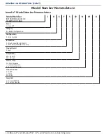
Page 18: ...OR MARKETING CHANNEL J B S F S 42 N M X Brand J JennAir Category B Built In Refrigeration Configuration S Side by Side Installation F Flush Install 84 Inch tall S Standard Install 84 Inch tall Produc...

Page 19: ...ATIONAL SALES OR MARKETING CHANNEL K B S D 70 8 M SS Brand K KitchenAid Category B Built In Refrigeration Configuration S Side by Side Product Detail D External Ice and Water N Non Dispenser Feature P...

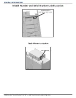
Page 20: ...tion 1 16 n JennAir and KitchenAid 36 42 and 48 Built In Side by Side Refrigerators Model Number and Serial Number Label Location Tech Sheet Location Model Number and Serial Number Label Location Tech...

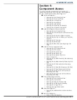
Page 21: ...Removing the Water Reservoir Dispensing Units Only Inside the Freezer Compartment FC Removing the Front Decorative Cover Removing the FC Thermistor Removing the Evaporator Cover Removing the Evaporato...

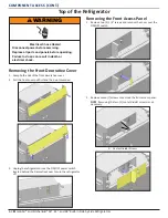
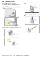
Page 22: ...ON OFF power switch located behind the Decorative Cover to turn the refrigerator off Removing the Front Access Panel 1 Remove two 2 1 4 screws and remove the cover over the ON OFF switch 2 Remove seve...

Page 23: ...1 3 from section Removing the Front Decorative Cover 2 Complete the steps 1 2 from section Removing the Front Access panel 3 Remove two 2 1 4 hex head screws from the power switch and humidity sensor...

Page 24: ...ated on the left and right hinge at the top of the doors 3 Remove two 2 phillips head mounting screws and remove the switch mounting bracket 4 Remove two 2 1 4 hex head screws from the front of the mo...

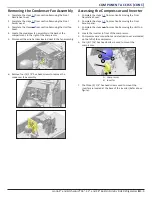
Page 25: ...o the fan assembly 6 Remove four 4 1 4 hex head screws to remove the condenser fan assembly Accessing the Compressor and Inverter 1 Complete the steps 1 3 from section Removing the Front Decorative Co...

Page 26: ...mounted inside the refrigerator compartment Open the refrigerator door and locate the UI in the center of the refrigerator compartment 2 To remove UI lift from the front then lift off the rear tabs 3...

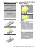
Page 27: ...to remove the assembly 3 Remove the gasket and foam to remove the air baffle Removing the RC Lower Air Diffuser and Thermistor Assembly 1 Remove drawer to locate the air diffuser assembly 2 Remove two...

Page 28: ...er Removing the RC Thermistor 1 Locate the Thermistor cover on the left side of the back wall 2 Pull on cover from the left side to remove 3 Thermistor is located inside cover Removing the LED Modules...

Page 29: ...ws holding the reservoir in place Inside the Freezer Compartment FC Removing the Front Decorative Cover 1 Complete the steps 1 3 from section Removing the Front Decorative Cover Removing the FC Thermi...

Page 30: ...enAid 36 42 and 48 Built In Side by Side Refrigerators Removing the Evaporator Cover 1 Remove all drawers and shelves below the ice maker 2 Remove four 4 sliders and eight 8 shelf studs Figure Removin...

Page 31: ...er Removing the Evaporator Fan 1 Complete the steps 1 3 from section Removing the Evaporator Cover 2 Remove the tape and piece of foam over the fan assembly 3 Remove four 4 1 4 hex head screws 4 Disco...

Page 32: ...or kit which has components available to splice into the existing thermistor harness Access to Evaporator 1 Complete the steps 1 3 from section Removing the Evaporator Cover 2 Complete the steps 1 6 f...

Page 33: ...e Heater Non dispensing Units Only 1 Complete the steps 1 4 from section Removing the Ice Maker Assembly Non dispensing Units Only 2 Disconnect the electrical connector and then remvoe the heater Remo...

Page 34: ...embly Dispensing Units Only 2 Complete the steps 1 3 from section Accessing the Ice Maker Water Inlet and Isolation Valves 3 Remove the water line from the ice maker water inlet valve by removing the...

Page 35: ...and then remove the cover 10 Inside the FC pull on fill tube to remove fill tube and water line Removing the Emitter Cover and Circuit Board Dispensing Units Only 1 Locate the Emitter on the outer wal...

Page 36: ...d screws to remove the emitter circuit board FC Door Dispensing Units Only Removing the Front Decorative Cover 1 Complete the steps 1 3 from section Removing the Front Decorative Cover Removing the Us...

Page 37: ...s 1 3 from section Removing the User Interface 2 Remove drip tray and then remove four 4 screws holding dispenser housing 3 Remove door skin by removing three 3 phillips screws on top six 6 phillips s...

Page 38: ...y 1 Complete the steps 1 3 from section Removing the User Interface 2 Remove two 2 1 4 hex head screws to remove the ice door motor assembly NOTE Disconnect the wire harness before removing the ice do...

Page 39: ...Refrigerator Accessing the Ice Maker Water Inlet and Isolation Valves Beneath the refrigerator behind the front grill are the water inlet valves There are two 2 possibly three 3 valves located togeth...

Page 40: ...move two 2 screws to remove the front grill 3 Remove two 2 1 4 hex head mounting screws from the front of the water valve housing then collect the water valve housing Figure Water inlet valves with Jo...

Page 41: ...lete the steps 1 3 from section Removing the Front Decorative Cover 2 Remove center back panel by removing six 6 1 4 hex head screws 3 Remove four 4 1 4 hex head screws to lower drain pan WARNING Elec...

Page 42: ...Component Access 4 22 n JennAir and KitchenAid 36 42 and 48 Built In Side by Side Refrigerators Notes...

Page 43: ...MBER READY TO IDENTIFY YOU AS AN AUTHORIZED IN HOME SERVICE PROFESSIONAL FOR LITERATURE ORDERS CUSTOMER EXPERIENCE CENTER PHONE 1 800 851 4605 FOR TECHNICAL INFORMATION AND SERVICE POINTERS www servic...

Page 44: ...JennAir and KitchenAid 36 42 and 48 Built In Side by Side Refrigerators W11636548 Rev A...

Reviews: