2
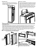
Fig. 4
Fig. 5
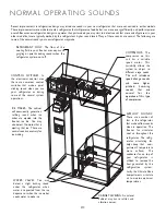
Water Line Installation:
Connect the water supply to the water valve. Turn the water
on and check for leaks. Plug the unit in. (Fig. 3)
Fig. 3
Leveling:
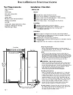
Slide the unit in place and raise the front and rear levelers
until the unit touches the brackets. Use a 3/8" socket for
raising and lowering the unit. On each wheel housing there
are two 3/8" hex bolts. On the left side, the outside bolt will
move the rear leveler and the inside bolt will move the front
leveler. On the right side, the outside bolt adjusts the front
leveler and the inside bolt will move the rear leveler (Fig. 4).
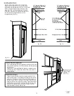
The front levelers must be in contact with the floor. To raise
the leveling legs, turn the hex screw in the counter clockwise
direction. Place a level on lower ledge of the machine
compartment. Level the unit front to back and side to side.
This is to prevent tipping of the unit (See Fig. 7). Install the
kickplate. Locate the main power switch in the machine
compartment and toggle the switch "On". Install the grille panel.
3/8"
Rear Leveler
Front Leveler
Kickplate
3 Phillips
Screws
GRILLE PANEL
MAIN POWER SWITCH
OR
3/8"
Fig. 2a
Fig. 2b
Uncrating the Unit:
Uncrate the unit. Remove the lower shipping bolts and brackets. Slide the unit off of the crate base. Remove and
save the lower kick plate, anti-tipping brackets and mounting hardware. (Fig. 2a) Remove the grille, this
will help when moving the unit. (Fig. 2b)
TOOLS NEEDED
REMOVE
KICKPLATE
REMOVE
SCREWS
Door
Panel
Lower Hinge
Plate
Door Stop
Mounting
Hole
90° Door
Stop
90° Door Stop
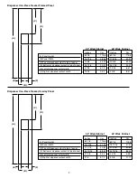
Both doors are designed to open 135°. To restrict one or both
doors to a 90° opening use the door stops supplied in this kit.
With the doors closed, screw a door stop into the underside
of the lower hinge plate (Fig. 5).
Yellow Valve
Blue Valve
Copper Water
Line
Water Valves


