background image

9

Parts Supplied

Check that all parts are included.

Propane/Natural Gas Conversion Kit

#10 x 1

5

/

8

" (4.1 cm) screws (for mounting anti-tip bracket) (2)

Anti-tip bracket (inside oven cavity)

Anti-tip bracket must be securely mounted to the back wall or
floor. Thickness of flooring may require longer screws to anchor
bracket to subfloor. Longer screws are available from your local
hardware store.

Parts needed

Check local codes and consult gas supplier. Check existing gas
supply and electrical supply. See “Electrical Requirements” and
“Gas Supply Requirements” sections.

IMPORTANT:

When the range is used under microwave models:

JMC82808CB-0, JMV9196CB-0, or YJMV9196CB-0, the Door
Baffle Plate Part Number W10737014 must be ordered and used.
Please reference the Quick Start Guide for contact information.

Optional parts

To purchase these or any other accessories, please reference the
Quick Start Guide for contact information.

Side Trim Kits:

5/8" (1.7 cm) White - Order Part Number W10675027
5/8" (1.7 cm) Black - Order Part Number W10675026
5/8" (1.7 cm) Stainless Steel - Order Part Number W10675028
1

1

/

8

" (2.9 cm) White - Order Part Number W10731885

1

1

/

8

" (2.9 cm) Black - Order Part Number W10731886

1

1

/

8

" (2.9 cm) Stainless Steel - Order Part Number W10731887

Backsplash Kits:

High 6" (15.2 cm) White - Order Part Number W10655448
High 6" (15.2 cm) Black - Order Part Number W10655449
High 6" (15.2 cm) Stainless Steel - Order Part Number
W10655450

NOTE:

Be sure to purchase only whirlpool factory-certified parts

and accessories for your appliance. Your installation may require
additional parts. To order, refer to the contact information
referenced in your Quick Start Guide.

Location Requirements

IMPORTANT:

Observe all governing codes and ordinances. Do

not obstruct flow of combustion and ventilation air.

It is the installer’s responsibility to comply with installation
clearances specified on the model/serial/rating plate. The
model/serial/rating plate is located behind the oven door on the
top right/left-hand side of the oven frame.

The range should be located for convenient use in the kitchen.

Recessed installations must provide complete enclosure of the
sides and rear of the range.

All openings in the wall or floor where range is to be installed
must be sealed.

Cabinet opening dimensions that are shown must be used.
Given dimensions are minimum clearances.

The anti-tip bracket must be installed. To install the anti-tip
bracket shipped with the range, see “Install Anti-Tip Bracket”
section.

Grounded electrical supply is required. See “Electrical
Requirements” section.

Proper gas supply connection must be available. See “Gas
Supply Requirements” section.

Contact a qualified floor covering installer to check that the
floor covering can withstand at least 200°F (93°C).

Use an insulated pad or 1/4" (6.4 mm) plywood under range if
installing range over carpeting.

IMPORTANT:

To avoid damage to your cabinets, check with your

builder or cabinet supplier to make sure that the materials used
will not discolor, delaminate or sustain other damage. This oven
has been designed in accordance with the requirements of UL
and CSA International and complies with the maximum allowable
wood cabinet temperatures of 194°F (90°C).

Mobile Home - Additional Installation
Requirements

The installation of this range must conform to the Manufactured
Home Construction and Safety Standard, Title 24 CFR, Part 3280
(formerly the Federal Standard for Mobile Home Construction and
Safety, Title 24, HUD Part 280). When such standard is not
applicable, use the Standard for Manufactured Home Installations,
ANSI A225.1/NFPA 501A or with local codes. In Canada, the
installation of this range must conform with the current standards
CAN/CSA-Z240.1, latest edition, or with local codes.

Mobile Home Installations Require:

When this range is installed in a mobile home, it must be
secured to the floor during transit. Any method of securing the
range is adequate as long as it conforms to the standards
listed above.

Summary of Contents for MGS8800PZ

Page 1: ...rawer On some models 17 Oven Door 17 Complete Installation 18 GAS CONVERSIONS 18 Propane Gas Conversion 19 Natural Gas Conversion 22 Adjust Flame Height 25 Moving the Range 27 S CURIT DE LA CUISINI RE...

Page 2: ...operty damage personal injury or death If a fire should occur keep away from the appliance and immediately call your fire department DO NOT ATTEMPT TO EXTINGUISH AN OIL GREASE FIRE WITH WATER The rang...

Page 3: ...ely follow instructions WARNING You can be killed or seriously injured if you don t follow instructions All safety messages will tell you what the potential hazard is tell you how to reduce the chance...

Page 4: ...ure Utensil Handles Should Be Turned Inward and Not Extend Over Adjacent Surface Units To reduce the risk of burns ignition of flammable materials and spillage due to unintentional contact with the ut...

Page 5: ...f any kind should be used in or around any part of the oven Clean Only Parts Listed in Manual Before Self Cleaning the Oven Remove broiler pan and other utensils Wipe off all excessive spillage before...

Page 6: ...re into the vent holes or down the back of the range METALLIC PAINT on some models Do not use abrasive cleaners cleaners with bleach rust removers ammonia or sodium hydroxide lye because paint surface...

Page 7: ...models Check that storage warming drawer is cool and empty before cleaning Cleaning Method Mild detergent OVEN CAVITY Use AquaLift Technology regularly to clean oven spills Do not use oven cleaners Fo...

Page 8: ...front frame to keep water from spilling onto the front of the range and the floor Soil baked on through several cooking cycles will be more difficult to remove with the Clean cycle Nonabrasive scrub s...

Page 9: ...ating plate The model serial rating plate is located behind the oven door on the top right left hand side of the oven frame The range should be located for convenient use in the kitchen Recessed insta...

Page 10: ...3 cm I 711 16 19 5 cm J 413 16 12 2 cm K 311 16 9 4 cm plus measurement of N L 12 30 5 cm M Cabinet door or hinges should not extend into the cutout N Remaining counter depth should not exceed 21 4 5...

Page 11: ...unded no keypads will operate Check with a qualified electrician if you are in doubt as to whether the metal chassis of the range is grounded Gas Supply Requirements WARNING Explosion Hazard Use a new...

Page 12: ...ply Pressure Testing Gas supply pressure for testing regulator must be at least 1 2 5 cm water column pressure above the manifold pressure shown on the model serial rating plate Line pressure testing...

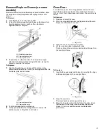
Page 13: ...ping base cardboard or hardboard from under range 7 Move range into its final location making sure rear leveling leg slides into anti tip bracket 8 Move range forward onto shipping base cardboard or h...

Page 14: ...on 1 Apply pipe joint compound made for use with Propane gas to the smaller thread ends of the flexible connector adapters see B and G in the following illustration 2 Attach one adapter to the gas pre...

Page 15: ...on the burner base Small cap Auxiliary Medium cap Semi Rapid Large cap Ultra Rapid X Large cap Stack Burner caps should be level when properly positioned If burner caps are not properly positioned su...

Page 16: ...o desired setting Check Operation of Oven Bake Burner 1 Press BAKE 2 Press the Start pad The oven burner should light within 8 seconds The first time a burner is lit it may take longer than 8 seconds...

Page 17: ...rawer in all the way 3 Gently open and close the storage drawer to ensure it is seated properly on the glides on both sides Oven Door For normal range use it is not suggested to remove the oven door H...

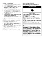
Page 18: ...alve is closed open it and then repeat the 5 minute test as outlined above If the gas supply line shut off valve is open close it and contact a qualified technician If You Need Assistance or Service P...

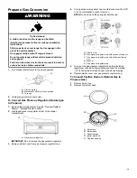
Page 19: ...rage Drawer section 2 Locate gas pressure regulator at rear of the drawer compartment A Gas pressure regulator IMPORTANT Do not remove the gas pressure regulator 3 Remove plastic cover from gas pressu...

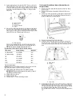
Page 20: ...the applicable individual burner BTU rating per fuel type 5 Place Natural gas orifice spuds in the orifice spud bag IMPORTANT Keep the Natural gas orifice spuds in case of reinstallation with Natural...

Page 21: ...ane gas broiler burner orifice hood turning it clockwise until snug IMPORTANT Do not overtighten A Orifice hood 6 Place the broil burner on the broil burner orifice hood Insert the broil burner cerami...

Page 22: ...Storage Drawer section 2 Locate gas pressure regulator at rear of the drawer compartment A Gas pressure regulator IMPORTANT Do not remove the gas pressure regulator 3 Remove plastic cover from gas pre...

Page 23: ...eep the Propane gas orifice spuds in case of reinstallation with Propane gas 6 Replace the burner base 7 Replace burner cap 8 Repeat steps 1 through 7 for the remaining burners To Convert Oven Bake Bu...

Page 24: ...th a 100 5 Replace the 100 hood with a 155 hood Install the Natural gas broiler burner orifice hood turning it clockwise until snug IMPORTANT Do not overtighten A Orifice hood 6 Place the broil burner...

Page 25: ...he low position to the high position checking the flame at each setting 5 Repeat the previous steps for each burner To Adjust Double Burner on some models 1 Light burner and turn to lowest setting whe...

Page 26: ...cavity behind the access panel Loosen the locking screw and rotate the air shutter until the proper flame appears Tighten locking screw A Locking screw B Air shutter 5 Push the Off pad when finished 6...

Page 27: ...ing range slide range onto cardboard or hardboard to avoid damaging the floor covering If removing the range is necessary for cleaning or maintenance For power supply cord connected ranges 1 Slide ran...

Page 28: ...poste t l phonique voisin Suivre les instructions du fournisseur de gaz Si le fournisseur de gaz n est pas joignable appeler les pompiers L installation et la r paration doivent tre effectu es par un...

Page 29: ...jours tre d tect es l odorat Les fournisseurs de gaz recommandent d utiliser un d tecteur de gaz approuv UL ou CSA Pour plus d informations contacter votre fournisseur de gaz Si une fuite de gaz est d...

Page 30: ...remplacer une quelconque pi ce de l appareil sans recommandation sp cifique du manuel Toutes les autres t ches d entretien doivent tre effectu es par un technicien qualifi Entreposage dans ou sur l a...

Page 31: ...Les autres surfaces de l appareil peuvent devenir suffisamment chaudes pour causer des br lures les ouvertures de ventilation et les surfaces autour de ces ouvertures les portes du four et les hublot...

Page 32: ...ini re PEINTURE M TALLIQUE sur certains mod les Ne pas utiliser de nettoyants abrasifs de nettoyants avec agent de blanchiment de produits antirouille d ammoniaque ou d hydroxyde de sodium soude car l...

Page 33: ...r action peut causer des taches des attaques des piq res ou de l g res taches blanches M thode de nettoyage D tergent doux TIROIR DE REMISAGE TIROIR R CHAUD sur certains mod les S assurer que le tiroi...

Page 34: ...ace en mail de l int rieur du four REMARQUE La cuisini re doit tre d aplomb afin que toute la surface du fond de la cavit du four soit recouverte par l eau au d but du programme de nettoyage Pour de m...

Page 35: ...s longues sont offertes chez votre quincaillerie locale Pi ces n cessaires V rifier les codes locaux et consulter le fournisseur de gaz V rifier l alimentation en gaz et l alimentation lectrique exist...

Page 36: ...93 C Dans le cas de l installation de la cuisini re sur une moquette placer sous la cuisini re un tapis isolant ou une plaque de contreplaqu de 1 4 po 6 4 mm IMPORTANT Pour viter d endommager les arm...

Page 37: ...I 7 11 16 po 19 5 cm J 4 13 16 po 12 2 cm K 3 11 16 po 9 4 cm plus la mesure N L 12 po 30 5 cm M La porte ou les charni res de l armoire ne doivent pas d passer l int rieur de l ouverture N La profon...

Page 38: ...joncteur diff rentiel en utilisation normale peut se produire du fait de la nature des cuisini res gaz allumage lectronique REMARQUE Le ch ssis m tallique de la cuisini re doit tre reli la terre pour...

Page 39: ...vec cette cuisini re doit tre utilis La pression d alimentation du d tendeur doit tre comme suit pour un fonctionnement correct Gaz naturel Pression minimale 5 po 12 7 cm de colonne d eau Pression max...

Page 40: ...a cuisini re a t d plac e Ne pas faire fonctionner la cuisini re si la bride antibasculement n est pas install e et engag e Le non respect de ces instructions peut causer un d c s ou des br lures grav...

Page 41: ...En cas d utilisation d un jeu de garnitures le dessus de la table de cuisson doit tre plus haut que le plan de travail Voir les instructions d installation fournie avec le jeu de garnitures pour la ha...

Page 42: ...ir le robinet d arr t manuel sur la canalisation d alimentation en gaz Le robinet est ouvert lorsque la manette est parall le au conduit d alimentation en gaz A Robinet ferm B Robinet ouvert 3 V rifie...

Page 43: ...lectronique est utilis la place des flammes de veille pour l allumage des br leurs table de cuisson et four Lorsque le bouton de commande de la table de cuisson est plac sur la position ignite allumag...

Page 44: ...trouvant dans la canalisation de gaz 4 Apr s 2 minutes ouvrir la porte du four et v rifier que le four est chaud Si les br leurs ne s allument pas correctement Appuyer sur la touche Off arr t V rifier...

Page 45: ...peuvent se trouver dans les mat riaux d emballage de la cuisini re 4 liminer recycler tous les mat riaux d emballage 5 V rifier que la cuisini re est d aplomb Voir la section Ajustement de l aplomb d...

Page 46: ...e entretien assume la responsabilit de l installation correcte de cet ensemble L installation ne peut tre consid r e comme ad quate et compl te qu apr s contr le satisfaisant du fonctionnement de l ap...

Page 47: ...jecteur du br leur A lectrode d allumage B Injecteur C Porte injecteur D Vis 4 Retirer les injecteurs fournis dans le sachet de documentation situ dans le four Chaque injecteur est marqu d un code d i...

Page 48: ...njecteur 47 par un injecteur 56 Installer l injecteur pour gaz propane du br leur de cuisson au four en le tournant dans le sens horaire jusqu ce qu il soit serr IMPORTANT Ne pas serrer excessivement...

Page 49: ...t c ne interne doit comporter une flamme bleue tr s distincte de 1 4 po 6 4 1 2 po 13 mm de long Le c ne ext rieur n est pas aussi net que le c ne int rieur Les flammes d un br leur aliment au propane...

Page 50: ...e sens antihoraire et soulever pour enlever l injecteur Conserver part l injecteur du br leur A lectrode d allumage B Injecteur C Porte injecteur D Vis 4 Chaque injecteur est marqu d un code d identif...

Page 51: ...ans le sens horaire jusqu ce qu il soit serr IMPORTANT Ne pas serrer excessivement A Injecteur 8 Positionner l arri re du br leur de cuisson au four sur l orifice du four et aligner les trous pour les...

Page 52: ...es 4 Voir la section Achever l installation des Instructions d installation de ce document pour achever cette proc dure IMPORTANT Conserver les gicleurs qui viennent d tre remplac s lors de la convers...

Page 53: ...tie inf rieure du four ter 2 vis l arri re de la partie inf rieure du four Soulever l arri re de la partie inf rieure du four vers le haut et l arri re jusqu d gager l avant du panneau hors du cadre a...

Page 54: ...sures mortelles Fixer la bride antibasculement au plancher ou au mur conform ment aux instructions d installation Faire glisser de nouveau la cuisini re de fa on ce que le pied arri re de la cuisini r...

Page 55: ...NOTES...

Page 56: ...NOTES...

Reviews: