background image

8

Before You Make the Electrical Connection:

To properly install your cooktop, you must determine the type of 
electrical connection you will be using and follow the instructions 
provided for it here.

A 4-wire or 3-wire, single phase, 120/240 volt, 60 Hz., AC only 
electrical supply on a separate, 40-amp circuit breaker is 
required for both 30" (76.2 cm) and 36" (91.4 cm) models. If a 
fused system is used, fuse both sides of the line. 

The cooktop should be connected directly to the junction box 
through the flexible metal conduit. The flexible, armored cable 
extending from the fuse box or circuit breaker box should be 
connected directly to the junction box.

Locate the junction box to allow as much slack as possible 
between the junction box and the cooktop so that the cooktop 
can be moved if servicing becomes necessary in the future.

A UL listed or CSA approved conduit connector must be 
provided at each end of the power supply cable (at the 
cooktop and at the junction box). 

If the house has aluminum wiring follow the procedure below:

1. Connect a section of solid copper wire to the pigtail 

leads.

2. Connect the aluminum wiring to the added section of 

copper wire using special connectors and/or tools 
designed and UL listed for joining copper to aluminum.

Follow the electrical connector manufacturer's recommended 
procedure. Aluminum/copper connection must conform with 
local codes and industry accepted wiring practices.

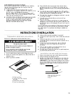
INSTALLATION INSTRUCTIONS

Prepare Cooktop

Decide on the final location for the cooktop.

1. Open product as instructed on product packaging.
2. Remove shipping materials and tape from cooktop.
3. Remove vent grille.

4. Remove the removable grease filter by lifting the filter out.
5. Using 2 or more people, remove the cooktop from the carton.
6. Use foam end caps from the packaging as a work surface for 

the floor or countertop.

7. Using 2 or more people, place the cooktop upside down on 

the foam end caps.

8. Make sure knobs are positioned in the open areas of the end 

caps.

9. Avoid placing the cooktop facedown on the control knobs.
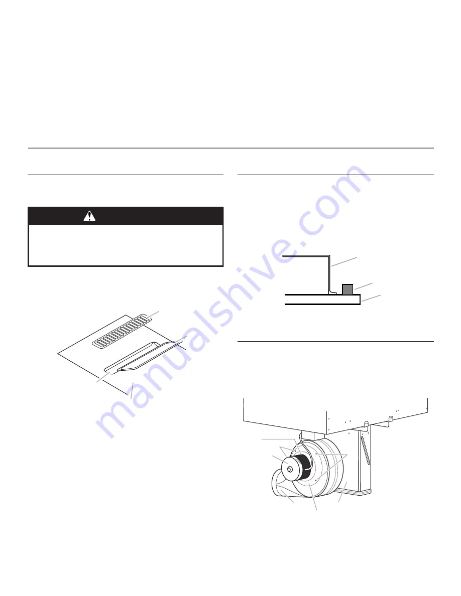
Install Foam Strip

1. Remove foam strip from the package containing literature. 
2. Remove backing from foam strip. 
3. Apply foam strip adhesive-side down around bottom of 

cooktop, flush with edge.
NOTE: The foam strip keeps the underside of the cooktop 
glass free from debris and helps the cooktop sit flat on uneven 
counters.  

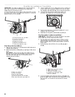
Rotate Blower - Optional

IMPORTANT: The following additional steps must be performed if 
the product is being installed in peninsula or island cabinetry.
The blower exhaust scroll is shipped from the factory set to 
exhaust straight out the back of the cabinet through an exterior 
wall.

A. Vent grille
B. Filter support tray (non-removable)

C. Removable grease filter
D. Ceramic glass top

WARNING

Excessive Weight Hazard

Use two or more people to move and install cooktop.

Failure to do so can result in back or other injury.

A

B

C

D

A. Cooktop base
B. Foam strip

C. Glass

A. Blower exhaust scroll
B. Plenum

C. Blower motor
D. Top label

E. 10-32 machine nuts (4)
F. Motor mounting plate

A

B

C

D

E

C

A

E

F

B

Summary of Contents for W10197059B

Page 1: ...Blower Optional 8 Install Cooktop 10 Make Electrical Connection 10 Complete Installation 11 S CURIT DE LA TABLE DE CUISSON 13 EXIGENCES D INSTALLATION 14 Outillage et pi ces 14 Exigences d emplacement...

Page 2: ...instructions are not followed Your safety and the safety of others are very important We have provided many important safety messages in this manual and on your appliance Always read and obey all safe...

Page 3: ...overning codes and ordinances When installing cooktop use minimum dimensions given To eliminate the risk of burns or fire by reaching over the heated surface units cabinet storage space located above...

Page 4: ...ecommended minimum cabinet to motor clearance G 16 41 6 cm H 4 11 8 cm A B C D E G F H A B C A B C D E G H F A 30 76 2 cm on 30 76 2 cm models 36 91 4 cm on 36 91 4 cm models B Combustible area above...

Page 5: ...ed Elbows too close together can cause excess turbulence that reduces airflow Do not use a 5 12 7 cm elbow in a 6 15 2 cm or 3 x 10 8 3 x 25 4 cm system Do not reduce to a 5 12 7 cm system after using...

Page 6: ...lete installation instructions For more information on the Jenn Air Duct Free Filter Accessory Kit contact your Jenn Air dealer or call 1 800 JENNAIR 1 800 536 6247 Option 1 Roof Venting Option 2 Wall...

Page 7: ...s and ordinances A copy of the above code standards can be obtained from National Fire Protection Association One Batterymarch Park Quincy MA 02269 CSA International 8501 East Pleasant Valley Road Cle...

Page 8: ...LLATION INSTRUCTIONS Prepare Cooktop Decide on the final location for the cooktop 1 Open product as instructed on product packaging 2 Remove shipping materials and tape from cooktop 3 Remove vent gril...

Page 9: ...d ratchet 6 Reinstall the four plastic plugs To rotate blower motor NOTE The Top label location on the blower motor is at the 9 o clock position 1 Using a ratchet with a socket and supporting the moto...

Page 10: ...Power Supply to 4 Wire Cable from Cooktop IMPORTANT Use the 4 wire cable from home power supply in the U S where local codes do not allow grounding through neutral New Branch circuit installations 19...

Page 11: ...d household cleaner and warm water to clean cooktop before use Dry thoroughly with a soft cloth For more information see the Cooktop Care section of the Use and Care Guide 5 Read Cooktop Use in the co...

Page 12: ...12 Notes...

Page 13: ...cas de non respect des instructions Votre s curit et celle des autres est tr s importante Nous donnons de nombreux messages de s curit importants dans ce manuel et sur votre appareil m nager Assurez...

Page 14: ...es dispositions de tous les codes et r glements en vigueur Lors de l installation de la table de cuisson utiliser les dimensions minimums indiqu es Afin de supprimer le risque de br lures ou d incendi...

Page 15: ...41 6 cm H 4 11 8 cm A B C D E G F H A B C A B C D E G H F A 30 76 2 cm sur les mod les de 30 76 2 cm 36 91 4 cm sur les mod les de 36 91 4 cm B Zone de mati re combustible au dessus du plan de travai...

Page 16: ...lation de l air Ne pas utiliser un coude de 5 12 7 cm dans un syst me de 6 15 2 cm ou 3 x 10 8 3 x 25 4 cm Ne pas r duire le syst me une longueur de 5 12 7 cm apr s avoir utilis des raccords de 6 15 2...

Page 17: ...tion concernant la trousse accessoire de filtration sans conduit Jenn Air contacter votre concessionnaire Jenn Air ou composer le 1 800 JENNAIR 1 800 536 6247 Option 1 D charge travers le toit Option...

Page 18: ...ous les codes et r glements locaux Pour obtenir un exemplaire des normes et codes ci dessus contacter National Fire Protection Association One Batterymarch Park Quincy MA 02269 CSA International 8501...

Page 19: ...tre conforme aux codes locaux et aux pratiques de c blage accept es par l industrie INSTRUCTIONS D INSTALLATION Pr paration de la table de cuisson D terminer l emplacement final de la table de cuisson...

Page 20: ...serr s 5 Resserrer chaque crou l aide de la douille de de la rallonge et de la cl cliquet 6 R installer les 4 bouchons d obturation en plastique Pour faire pivoter le moteur du ventilateur REMARQUE L...

Page 21: ...tions de raccordement lectrique pour terminer l installation correspondant votre type de raccordement lectrique Options de raccordement lectrique C ble 4 conducteurs depuis le point de distribution du...

Page 22: ...l es S il reste une pi ce passer en revue les diff rentes tapes pour d couvrir laquelle aurait t oubli e 2 V rifier la pr sence de tous les outils 3 Jeter recycler tous les mat riaux d emballage 4 Uti...

Page 23: ...23 Notes...

Page 24: ...r serv s Registered Trademark TM Trademark of Jenn Air U S A Used under license by Maytag Limited in Canada Marque d pos e TM Marque de commerce de Jenn Air U S A Emploi sous licence par Maytag Limite...

Reviews: