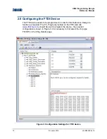
Jennic
USB Programming Dongle
Reference Manual
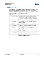
2.7 Extended Connector
The connector J1 is an alternative connector to J8. It has the same signals as J8
with the addition of DIO4 and DIO5, which can form the RTS and CTS UART
connections associated with DIO6 and DIO7. This connector employs 3.3V signals,
except the VCC signal is 5V (while it is 3.3V on the J8 connector). The connector
takes the physical form of 8 pads at a 2.54-mm pitch.
Pin Name
Use
1 RESETN
(output)
Control line to connect to RESETN of the JN5148 - used in
conjunction with MISO to put remote JN5148 into programming
mode. Also used to reset the JN5148 after a programming cycle. It
is only possible to cause this pin to go low, due to the diode D4.
2 GND
Ground
3 DIO5
(input)
CTS UART signal – to connect to remote UART0 RTS output,
i.e. DIO5 of JN5148.
4
VCCUSB
5V from the USB connector.
5 DIO7
(output) Transmit UART data, to connect to UART0 RXD input of the
JN5148, i.e. DIO7.
6 DIO6
(input)
Receive UART data, to connect to UART0 TXD output from remote
JN5148, i.e. DIO6.
7 DIO4
(output) RTS UART signal – to connect to remote UART0 CTS input,
i.e. DIO4 of JN5148.
8 MISO
(output) Control line to connect to SPIMISO of the JN5148 – used in
conjunction with RESETN to put remote JN5148 into programming
mode. It is only possible to cause this pin to go low, due to diode D5.
Table 3: Pinout of J8 Connector
JN-RM-2056 v1.0
© Jennic 2010
9


