Check Box When This Step is Complete
INSTALLATION INSTRUCTIONS
Step # 22
CONNECTING THE ELECTRICAL CONNECTIONS OF THE CONSOLE
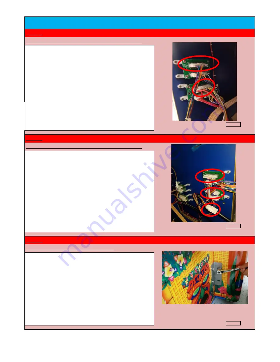
There are two connections that need to me made on the right side of
the player console. There is a 10 Pin connector (with 9 wires) that
plugs into the upper board and a 12 pin connector (with 11 wires) that
plugs into the bottom board. The connections required to be made
are circled in the photo on the right.
Check Box When This Step is Complete
Step # 23
CONNECTING THE ELECTRICAL CONNECTIONS OF THE CONSOLE
There are three connections that need to be made on the left side of
the player console. There is a 10 Pin connector (with 9 wires) that
should be plugged into the upper board. There is a 12 Pin connector
(with 11 wires) that should be plugged into the lower board. Finally,
there is a 3 Pin high voltage AC Molex connection for the bill acceptor.
Check Box When This Step is Complete
Step # 24
SECURING THE CONSOLE TO THE MAIN CABINET
After installing the wired connections on both left and right side,
carefully move the player console to the main cabinet making sure all
wires are safely inside the two cabinets and not stuck between them.
Then using the supplied M8 bolts, attach the console "L" bracket to
the player console and then to the main cabinet. Repeat this step on
the other side to secure the player console.
JET Games
Kahuna's Big Wave Service Manual
19


