background image

OFF

NOTICE

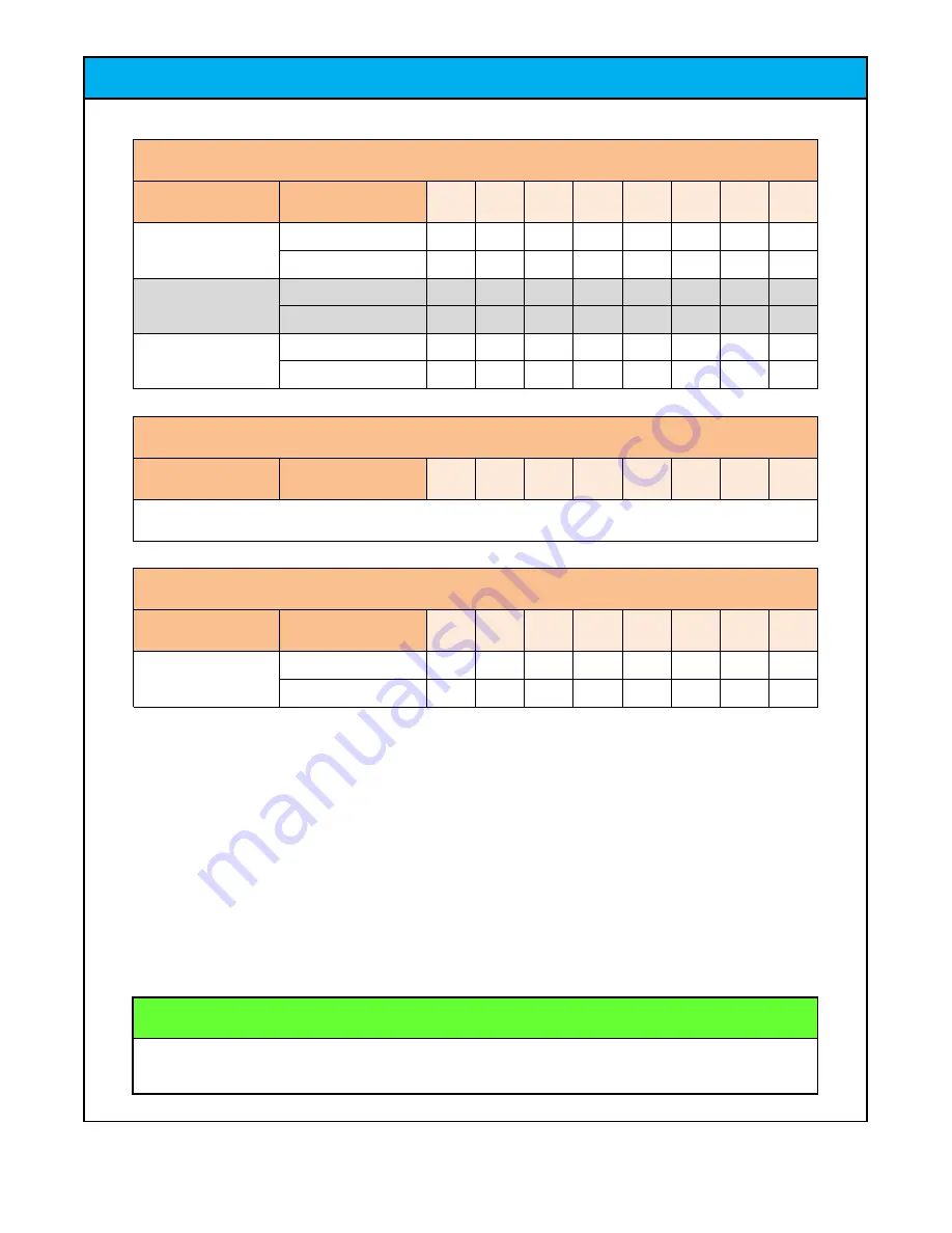
DIP SWITCH #2 IS NOT CURRENTLY UTILIZED IN KAHUNA'S BIG WAVE

DIP SWITCH SETTINGS

SWITCH # 1 (SW1)

DESCRIPTION

VALUE

SW11 SW12 SW13 SW14 SW15 SW16 SW17 SW18

SWITCH # 2 IS NOT USED IN KAHUNA'S BIG WAVE

COMMUNICATE

OFF

STOP 1 TIME

NOT COMMUNICATE

ON

ON

SEG DISPLAY 

FUNCTION

STOP 2 TIMES

ON

CHAIN SELF TEST

GAME FUNCTION

NORMAL GAMEPLAY

OFF

TEST CODE - NO PC

SWITCH # 2 (SW2)

DESCRIPTION

VALUE

SW21 SW22 SW23 SW24 SW25 SW26 SW27 SW28

SWITCH # 3 (SW3)

DESCRIPTION

VALUE

SW31 SW32 SW33 SW34 SW35 SW36 SW37 SW38

ON

TEST MODE

OFF

GAME MODE / TEST 

MODE

GAME MODE

JET Games

Kahuna's Big Wave Service Manual

46

Summary of Contents for Kahuna's Big Wave

Page 1: ...rvice Email Service JennisonGames com Phone Number 1 386 255 1599 www JENNISONGAMES com For Additional Information or for an Electronic Copy of This Manual Visit Our Website Jennison Entertainment Tec...

Page 2: ...8 9 RoHS Compliance Cabinet Dimensions Electrical Requirements Installation Instructions 48 4 Section Page Safety Notifications Epilepsy Warning 4 2 3 Table of Contents 43 7 TABLE OF CONTENTS 41 Warn...

Page 3: ...are in BLUE These messages are provided in cases where service personal must follow directions provided by J E T NOTICE Notices are given in GREEN boxes These messages are provided for the operator s...

Page 4: ...n eye or face twitching jerking or shaking of arms or legs disorientation confusion or momentary loss of awareness Seizures may also cause loss of consciousness or convulsions that can lead to injury...

Page 5: ...rvice department DANGER KAHUNA S BIG WAVE SAFETY CAUTIONS NOTICES DANGER DO NOT perform repairs or maintenance on the game with the power ON Always turn the power OFF and unplug the unit from the wall...

Page 6: ...s capacity CAUTION Use appropriate care when servicing the game and ensure that all removed components are away from facility guests and children KAHUNA S BIG WAVE SAFETY CAUTIONS NOTICES Set the 115...

Page 7: ...igital apparatus meets all requirements of the Canadian Interference Causing Equipment Regulations Cet appareil num rique da la classe A respecte toutes les exigences du R glement sur le mat riel brou...

Page 8: ...s Big Wave As of November 2019 Jennison Entertainment Technologies has tested all components used in the manufacturing of Kahuna s Big Wave All components have been found to be within the standards se...

Page 9: ...omfortably fit Do not push on the front of the main cabinet as there is a large Acrylic cover on 3 sides of the cabinet with two monitors inside WEIGHT HEIGHT WIDTH LENGHTH KAHUNA S BIG WAVE CABINET D...

Page 10: ...FERENT LINE VOLTAGE THAT IT WAS AT INITIAL TIME OF DELIVERY YOU MUST ALSO SELECT THE NEW INPUT AC VOLTAGE ON ALL POWER SUPPLIES AND SPEAKER AMPLIFER KAHUNA S BIG WAVE ELECTRICAL REQUIREMENTS HERTZ AMP...

Page 11: ...OUR DISTRIBUTOR PRIOR TO CONTINUING NEITHER J E T NOR YOUR DISTRIBUTOR IS RESPONSIBLE FOR ANY DAMAGE CAUSED DURING IMPROPER INSTALLATION PROCEDURES RED SECTIONS RED SECTION AREAS REQUIRE 3 OR MORE PEO...

Page 12: ...s from the bottom of the inside lip of the section 4 The top picture to the right will show how the screws are mounted and they must be removed to prevent damage to the Acrylic bottom The Bottom pictu...

Page 13: ...s placed on the main cabinet Make sure to lift the unit over the cabinet and not slide the Section 3 so you do not scratch the cabinet Once it is on top of the main cabinet position it so it lines up...

Page 14: ...st be pushed in all the way and indexed with connections aligned left to right After securing Section 3 to the main cabinet open up the rear access doors and clear away any packaging material from aro...

Page 15: ...lic ramps Once again be mindful not to accidentally push out any pins Check Box When This Step is Complete Step 11 CONNECTING THE ELECTRICAL CONNECTIONS Ensure that both connections are properly made...

Page 16: ...seated and in the center of the connector board Check Box When This Step is Complete The Section 4 Marquee header bolts to the Section 3 Ball holding header There is a total of 6 Machine screws used t...

Page 17: ...before lifting the marquees into place at the top of the game INSTALLATION INSTRUCTIONS Step 16 Check Box When This Step is Complete Step 18 CONNECTING THE SIGN ELECTRICAL CONNECTIONS After installing...

Page 18: ...After unwrapping the player console from the shipping foam roll the unit over to the main cabinet leaving yourself enough room to make the electrical connections needed DANGER Check Box When This Step...

Page 19: ...de of the player console There is a 10 Pin connector with 9 wires that should be plugged into the upper board There is a 12 Pin connector with 11 wires that should be plugged into the lower board Fina...

Page 20: ...The game should start and run after the computer goes thought its diagnostic process This could take up to two minutes while Windows loads and the software starts Once the software loads it will go th...

Page 21: ...n ticket meter assembly Locate the Coin Ticket meter assembly mounted to the top of the cash box Push and hold the green ENTER button on the right of the assembly to enter the program mode menu PROGRA...

Page 22: ...he most current software version available You can view the software version operating on the game from within the program settings The software version is posted on the bottom right of the screen for...

Page 23: ...yer 1000 Type 2 Type 2 Big Wave Bonus displays a shorter fanfare and the total value of tickets won It does not drop any balls to make the bonus sequence longer Step 7 Selecting the Big Wave Bonus mod...

Page 24: ...the LIL TIKI BONUS DO NOT ALTER THE LOCATION OF THE BONUS AS IT WILL ALTER THE PROGRAM THE BIG WAVE BONUS MUST STAY IN POSITION 6 AND THE LIL TIKI MUST BE IN POSITION 2 Removing these should only be...

Page 25: ...e playfield and screen values The value at the bottom is the value awarded for any ball that does not fall into a target and rolls off the edge The operator can also change the location of the LAVA BO...

Page 26: ...ff the edge Please note that if you divide tickets the value you select on this screen should be divisible For example if you select 2 point tickets each value selected should be even Selecting game s...

Page 27: ...ave Bonus Value This feature allows the operator to change the value of the Big Wave bonus This value is displayed on the red four digit SEG display in the overhead marquee Any ball that successfully...

Page 28: ...ll have 5 tickets added to it after each game play If this value is set to 0 no additional tickets will be awarded and the value programmed in Step 12 will be what is won JET does not suggest adding t...

Page 29: ...MUST enter the cost per credit and the cost per ticket If this information is NOT entered when these values are reset the calculated amount will not be correct This page should only used as a backup...

Page 30: ...f win since last reset Player one information is shown on the LEFT screen and player two information is shown on the RIGHT screen Individual or the combined data can be reset if desired Step 16 Select...

Page 31: ...the percentages If you charge USD1 00 to play the game and your card system is set to one pulse understand that your credit will be worth USD1 00 this value must be set properly in Step 14 in order to...

Page 32: ...mber of balls per credit and then award an incentive for additional credits if entered at the same time For example 1 ball is given for one credit and 3 balls are awarded for two credits Please note t...

Page 33: ...s volume The operator can adjust the volume of the GAME PLAY SOUNDS from selecting a value within this feature Please note that 100 is the highest value while 0 is the lowest Also note that the volume...

Page 34: ...value while 0 is the lowest If you select 0 you will NOT hear any attract sound features Step 23 Selecting ticket out sounds Selecting either ON or OFF will determine whether additional sounds are pla...

Page 35: ...o win Bridge UP Bridge DOWN Time Interval This is the number of seconds the bridge is up or down Bridge Chain Time Interval Chain time interval JET suggests 0 PROGRAM SETUP INFORMATION Step 24 Selecti...

Page 36: ...s and outputs for the game Each time an input is triggered the corresponding target on this screen should illuminate or display 1 instead of 0 If it does that indicates the sensor and the input IC is...

Page 37: ...feature will clear all credits owed within the program for both player one and player two Step 27 Clearing tickets owed Selecting this feature will clear all tickets owed within the program for both p...

Page 38: ...elected settings Step 29 Software restart After exiting the program the software will restart You should see a screen wash and then the JET logo will appear When completed and NO link messages display...

Page 39: ...T SIGNAL 4 PLAYER 1 TICKET FEEDBACK SIGNAL 1 5 8 PLAYER 1 BRIDGE SENSOR LEFT SCREEN SENSOR R X 13 11 PLAYER 1 BALL TRACK RELEASE SWITCH 12 U10 17 18 19 20 21 22 23 24 PLAYER 2 PLAY BUTTON PLAYER 2 BRI...

Page 40: ...ive IC JET suggests replacing with a new chip first and not pulling one from another part of the I O board MAIN BOARD INPUTS CONTINUED KAHUNA S BIG WAVE MAIN BOARD INPUT CHART CONTINUED IC INPUT CONTE...

Page 41: ...27 PLAYER 2 LOWER BALL RELEASE SOLENOID 28 PLAYER 2 SPOTLIGHT 29 30 PLAYER 2 BRIDGE MOTOR 31 PLAYER 2 CHAIN SCORE HOLE LED 32 PLAYER 2 CHAIN MOTOR DIRECTION PLAYER 1 CHAIN MOTOR PLAYER 1 BLOWER PLAYER...

Page 42: ...37 PLAYER 2 TICKET DRIVER 1 38 PLAYER 2 TICKET INDICATOR LIGHT 39 PLAYER 1 COIN CREDIT LOCK 40 PLAYER 2 COIN CREDIT LOCK Q9 Q16 41 GROUND LED RED 42 GROUND LED GREEN 43 GROUND LED BLUE 44 PLAYER 1 BUT...

Page 43: ...SEG 1 8 PLAYER 2 SCORE X 1000 SEG 2 8 PLAYER 1 SCORE X 1000 SEG 2 4 LITTLE TIKI BONUS SCORE X 1000 SEG 1 5 PLAYER 2 SCORE X 1 PLAYER 1 SCORE X 1 SEG 2 1 LITTLE TIKI BONUS SCORE X 1 SEG 1 2 PLAYER 1 S...

Page 44: ...IG WAVE COMMUNICATE OFF STOP 1 TIME NOT COMMUNICATE ON ON SEG DISPLAY FUNCTION STOP 2 TIMES ON CHAIN SELF TEST GAME FUNCTION NORMAL GAMEPLAY OFF TEST CODE NO PC SWITCH 2 SW2 DESCRIPTION VALUE SW21 SW2...

Page 45: ...E X 1 PLAYER 2 SCORE X 1000 SEG 2 8 SEG 1 5 PLAYER 2 SCORE X 1 SEG 2 5 SEG 1 7 PLAYER 2 SCORE X 100 SEG 2 7 SEG 1 2 PLAYER 1 SCORE X 10 SEG 2 2 LITTLE TIKI BONUS SCORE X 10 SEG 1 3 SEG 2 4 SEG 1 6 PLA...

Page 46: ...commended to rectify the problem Before contacting your distributor please check to make sure that the unit is in fact plugged in and receiving power and that there are no loose connections Should you...

Page 47: ...upgraded speakers Step 1 Receiving the Update Kit Each update ships complete from JET Games with two BOSE speakers both left and right The kit will ship in the retail packaging from the manufacturer...

Page 48: ...mount Secure the mount to the speaker using the included hardware as shown NOTE The speakers should be mounted so that they curve inward towards the middle of the cabinet The speaker shown in this pho...

Page 49: ...ll limit how far it can be removed Be careful to not pull too hard and pull out any wire connections Step 7 Removing the Back Plate Using either a flat headed screw driver or utility knife carefully l...

Page 50: ...sure the bolts are tight Please ensure that the bracket is flush with the back of the sign It does not matter if this bracket sticks out further on the bottom BOSE SPEAKER INSTALLATION INSTRUCTIONS St...

Page 51: ...et using the included hardware and ensure it is tight Check to make sure the top of the bracket is flush with the rear of the sign Carefully put the back plate back onto the rear of the sign You may n...

Page 52: ...ng Bracket Step 16 Drilling the Wire Harness Holes Using the same drill bit drill a hole into the upper left section 3 acrylic window This hole is used to route the speaker wire out of the cabinet and...

Page 53: ...ct both wires to the proper ports on the back side of the speaker Locate the speaker harness and route the end through the new hole that was drilled Repeat this process on the opposite side Secure the...

Page 54: ...e New Harness Unplug the existing speakers and plug the new speaker harness and its three pin connector into the existing speaker wire connector You will not remove the old speaker s They can remain i...

Page 55: ...rom JET JET Games will share a ONEDRIVE link with you where the entire game folder can be copied to a thumb drive Contact JET for this link If the file is zipped unzip the file as you save it to your...

Page 56: ...der Navigate to the BIG WAVE folder SOFTWARE UPDATE INSTRUCTIONS Step 3 Exiting the Software With the keyboard close to the transceiver press ALT and F4 at the same time This will exit the software an...

Page 57: ...ill allow us to go back should there be a problem COMPUTER LOCAL DISK C BIGWAVE EN Step 7 Copying over the New Software Open the REMOVEABLE storage device and open the folder you downloaded from the J...

Page 58: ...PHOTO NOT PROVIDED Power cycle the game and ensure that when Windows starts the software loads properly Step 11 Checking the New Software Version After the software loads enter into the menu and check...

Page 59: ...e Back Plate Carefully put the back plate back onto the rear of the sign You may need to use your utility knife to get the piece back into the correct position Slowly re insert all 10 screws holding t...

Page 60: ...ket This bracket is used to secure the sign to the marquee header unit Ensure that all four screws are tight Step 16 Drilling the Wire Harness Holes Using the same drill bit drill a hole into the uppe...

Page 61: ...er to the bracket using the provided screw Do not let go of the speaker until it is firmly mounted in place BOSE SPEAKER INSTALLATION INSTRUCTIONS Step 18 Threading the Speaker Wire Locate the speaker...

Page 62: ...ew Harness Unplug the existing speakers and plug the new speaker harness and its three pin connector into the existing speaker wire connector You will not remove the old speaker s They can remain in p...

Reviews: