Pointer Sensor Issue
Step # 6
Pointer Sensor Issue
Fixing a Pointer Sensor Issue
Step # 7
Pointer Sensor Issue
Step # 5
If all voltages from the pointer sensor
check out properly, and all red LED's turn
on and off properly then we can assume
the sensor is working properly. We then
need to check continuity of the sensor
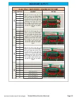
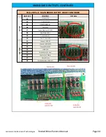
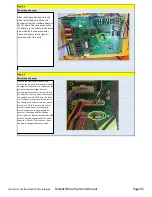
signal wires from the sensor connection (6
pin connector on sensor) in the front of the
cabinet to the Sensor connections at the
wheel interface board in the back. You can
see from the picture to the right that the
Yellow wire is connection 3, Green wire is
connection 4, and Blue wire is connection
5. All sensor connection is the top two 8 pin
connectors.
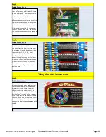
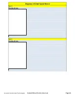
After checking for continuity from the
sensor to the wheel interface board you
can check from the wheel interface board
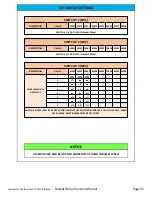
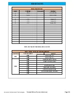
down to the I/O board. The wires will be
inputs number 18, 19, 20. If you get
coninuity all the way from the sensor to
the I/O board, and the sensor operates
properly then please swap out the input
chip in the U10 position. Your spare input
chips are in the U11, and U12 locations.
Please pay attention to the indention in the
chips when reinstalling as these chips only
work one way.
If all Steps above check out properly, and
all connections and power readings are in
specification. The problem could be the
adjustment in the distance the pointer
magnet is from the pointer sensor. To
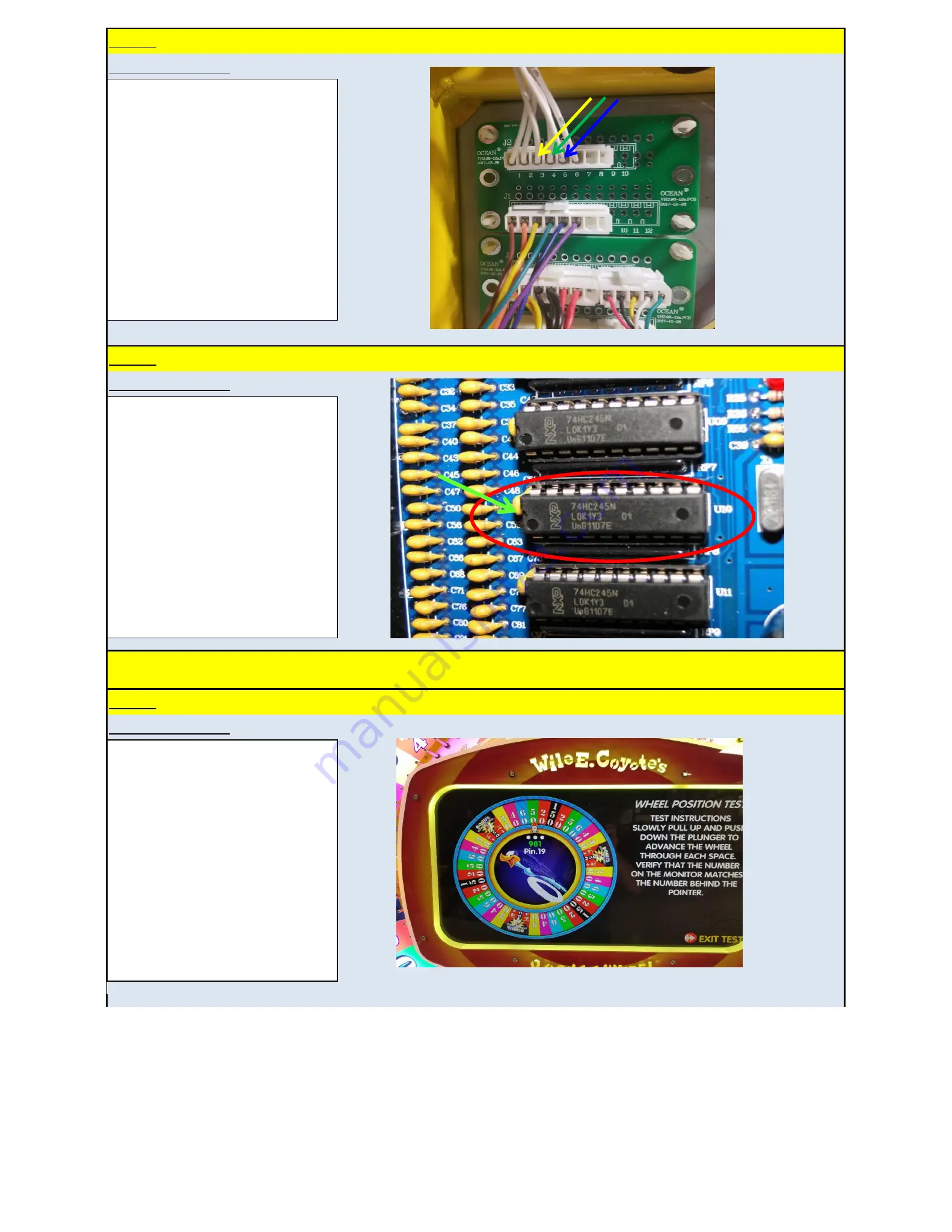
check this we will have to do the "Wheel
Posistion Test" in step 20 of the program
setup. The pointer on the monitor should
click over at the same time as the physical
pointer of the game. If not remove the
clear acrylic wheel cover and proceed with
step #8.
Jennison Entertainment Technologies
Rocket Wheel Service Manual
Page 42


