JWM6
0A
Auxiliary Input Function
Auxiliary Input Connector
USB Interface Connector
Clock Display
Clock Setup
Sleep Mode
Alarm Setting
Remote Sensor
Speaker Output
Reset
Press the
AUX
button (26) to directly access auxiliary input modes (AUX IN1 and
AUX IN2) from any other mode when a portable audio device is connected to the
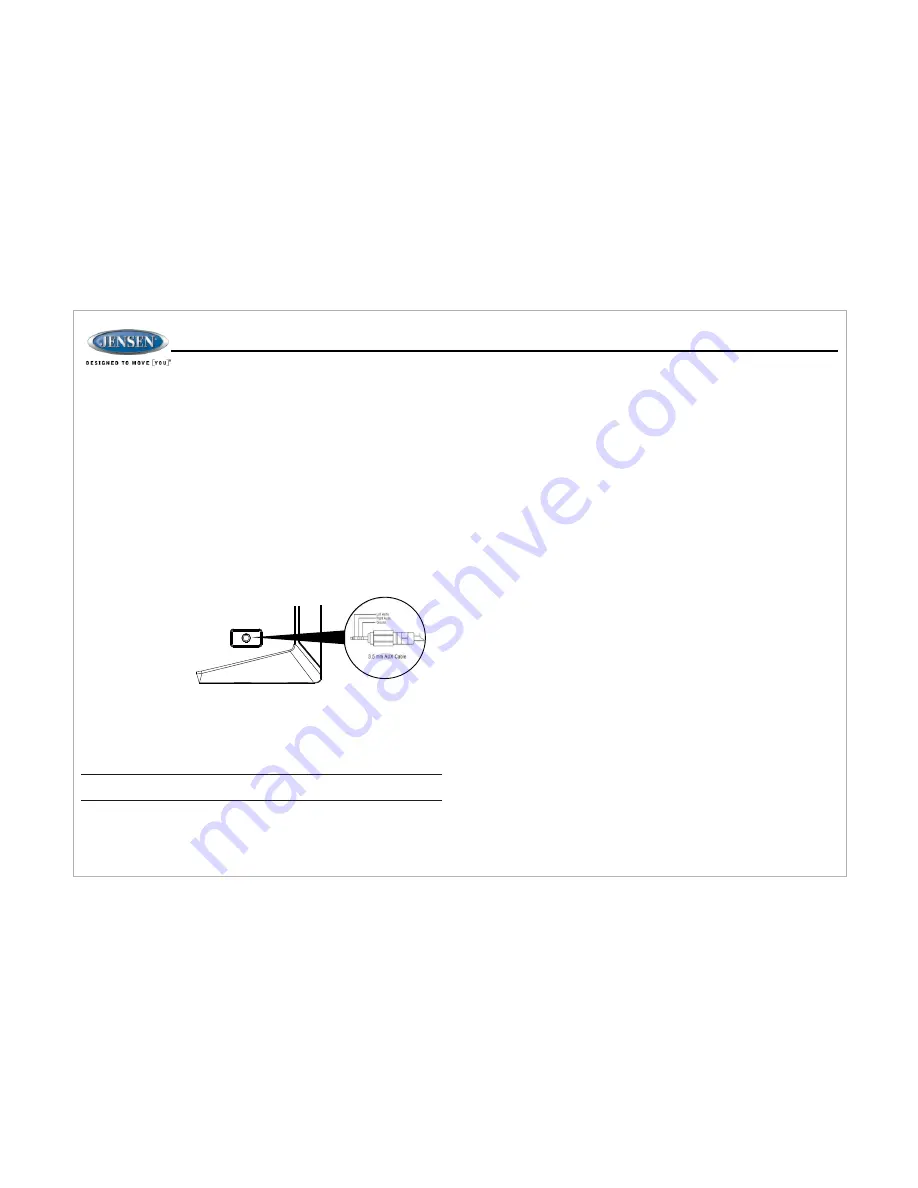
unit. To connect a portable audio device, insert a standard 3.5mm (audio line
output or headphone output from your portable CD / MP3 / iPod or other media
player) into the AUX A/V IN connector (AUX IN1) (26) on the front of the unit or
the AUDIO IN (AUX IN2) on the back of the unit (see
“
Wiring
”
on page 3).
For front panel A/V input, an external audio/video (A/V) source such as a video
game player, camera, etc. can be connected to the front panel A/V input with the
provided 3.5mm A/V cable adapter (Please note that there are several different
A/V cable "standards"). Connect the device to the AUX A/V IN connector (26) on
the front panel.
In addition to front panel auxiliary input source, the unit can also be connected
to the RCA audio input through the AUX AUDIO INPUT jack on the rear of the
unit.
Press the
AUX
button (26) to directly access auxiliary input modes (AUX 1 IN
and AUX 2 IN) from any other mode when a portable audio device is connected
to the unit.
You can connect a USB device directly to USB interface (16) on the front of the
JWM60A for playback of compatible files. Playback begins automatically. Press
the USB button (
) to switch to USB mode from another source. Refer to
16
“MP3/USB Operation” on page 13 for additional operating instructions.
Press the
VIEW
button (4) to alternate between playing time and clock time while
in Tuner, CD, DVD, USB or auxiliary input mode.
NOTE: USB will not support Apple device playback. The USB input supplies
up to 1A of charging current.
Press and hold the clock
HOUR
or
MINUTE
button (39, 36) to access clock setup
mode. The number representing the hours and minutes will flash. Press the
HOUR
button (39) to adjust the hour and press the
MINUTE
button (36) to adjust minutes.
The new time will be saved five seconds after the last adjustment is made.
The Sleep Timer will automatically turn off the JWM60A in the designated number of
minutes. To set the Sleep Time, press the
SLEEP
button (37) and the sleep time will
appear in the display with the number representing the minutes (SLEEP 0). Press
SLEEP
button repeatedly to change the sleep time from 0 (OFF), 15, 30, 45 or 60
minutes.
To set the alarm, press and hold the
ALARM SET
button (38) for 2 seconds and the
clock digits will be flashing. Press the
HOUR
button to adjust the hour once at a time
or press and hold to advance rapidly. Repeatedly press the
MINUTE
button to adjust
the minute one digit at a time, or press and hold to advance rapidly.
Press the
ALARM SET
or
ENTER
knob button to save the alarm time.
Once a time is set, press
ALARM ON/OFF
(38) to turn the alarm function on or off.
Infrared receiver is located on the upper left of front panel to receive infrared signal
emitted by the remote control.
The three speaker output buttons (19, 21, 23) (Zone A, Zone B and Zone C) control
speaker zones output from the radio. Press any of the three buttons to turn the
corresponding speaker zone on or off. SPK A (Zone A), SPK B (Zone B) or SPK C
(Zone C) will appear on the display.
The reset button should be activated for the following reasons:
•
initial installation of the unit when all wiring is completed
•
function buttons do not operate
•
error symbol on the display
Use a ball point pen or similar object to press the
RESET
button (28). This may be
necessary should the unit display an error code.
8
Summary of Contents for JWM60A
Page 1: ...Installation and Owner s Manual MOBILE AUDIO SYSTEM JWM60A ...
Page 2: ......
Page 24: ......


