background image

3

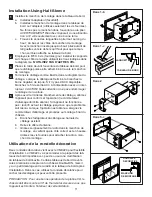
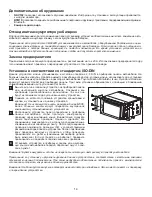
Installation Using Half-Sleeve

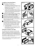
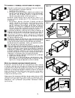
  Install half-sleeve in the dashboard.

a.  Install adapter if necessary (optional).
b.  Install half-sleeve into adapter or dashboard (use only 

the supplied screws). Do not force the sleeve into the 
opening or cause it to bend or bow.

WARNING! Only connect the unit to a 12-volt power 
supply with proper grounding.

c. 

Locate the series of bend-tabs along the top, bottom 
and sides of the mounting sleeve. With the sleeve fully 
inserted into the dashboard opening, bend as many of 
the tabs outward as necessary so that the sleeve is 
fi rmly secured to the dashboard.

  Use the M5 x 6 screws (provided) to install the mounting  


brackets to each side of the radio using the holes indicated 

 in 

the 

diagram. 

DO NOT USE OTHER SCREWS.

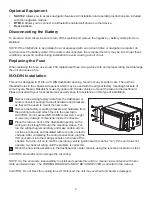
  Place the radio in front of the dashboard opening so the 


wiring can be brought through the mounting sleeve.

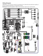
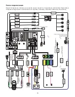
  Complete wiring as illustrated in the wiring diagram. Once  


the wiring is complete, reconnect the battery negative 


terminal. If there is no ACC available, connect the ACC lead  


to the power supply with a switch.


CAUTION! Be careful not to damage the car wiring.

  After completing the wiring connections, turn the unit on

 to 

confi rm operation (ignition switch must be on). If unit does  


not operate, recheck all wiring until problem is corrected.  


Once proper operation is achieved, turn off the ignition  


switch and proceed with fi nal mounting of the chassis.
a.  Connect wiring adapter to existing wiring harness.
b.  Connect antenna lead.
c. 

Carefully slide the radio into the half-sleeve, making 
sure it is right-side-up. Use the supplied screws to at-
tach the radio to the half sleeve.

Using the Cosmetic Trim Ring

Two cosmetic trim rings are packaged with the head unit for 
installation fl exibility. This unit will fi t into most import dashes 
with little or no modifi cation to the dash board/cavity. Some US 
domestic vehicle dashes will accept a Double-DIN chassis, but 
there is usually a small gap between the radio and dash piece af-
ter installation is complete. In this case, use the appropriate trim 
ring to conceal any gaps that may be present.

NOTE: For proper operation of the CD/DVD player, the chassis 
must be mounted within 30° of horizontal. Make sure the unit
is mounted within this limitation.

1

2

3

4

5

DASHBOARD

TAB

Step 1-b

Step 1-c

Step 2

Step 5-c

MOUNTING
SLEEVE

TRIM RING

Summary of Contents for VM9224R

Page 1: ...ilips screwdrivers Wire cutters and strippers Tools to remove existing radio screw driver socket wrench set or other tools Electrical tape Crimping tool Volt meter test light Crimp connections 18 gaug...

Page 2: ...r stereo specialty shop for assistance on this type of installation Remove the existing factory radio from the dashboard or center console mounting Save all hardware and brackets as they will be used...

Page 3: ...UTION Be careful not to damage the car wiring After completing the wiring connections turn the unit on to confirm operation ignition switch must be on If unit does not operate recheck all wiring until...

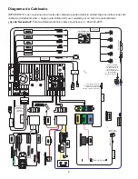
Page 4: ...MUTE BATT ACC REAR R FRONT L REAR L FRONT R FRONT R FILTER FUSE 20A BLUE GREEN YELLOW PINK BRAKE BLUE WHITE BLUE P CONT ANT CONT ANT CONT Steering Wheel Control SWC requires PAC SWI PS Interface Adap...

Page 5: ...de Energ a Dos arn s de accesorio Instruccionnes de Instalaci n Qu hay en la Caja Necesitar estas herramientas y suministros para instalar su VM9224R Destornilladores del tipo Torx cabeza plana y Phi...

Page 6: ...del tablero el radio existente de f brica o centre la consola de montaje Guarde todos los elementos y m n sulas pues ser n utilizados para montar el nuevo radio Quite las m nsulas y elementos de mont...

Page 7: ...CAC al suministro de energ a con un interruptor Tenga cuidado de no da ar el cableado del autom vil Despu s de terminar las conexiones de cableado enci enda la unidad para confi rmar el funcionamiento...

Page 8: ...GND MUTE BATT ACC REAR R FRONT L REAR L REAR L FRONT R FILTER FUSE 20A AZUL VERDE AMARILLO ROSA BRAKE AZUL BLANCO AZUL P CONT ANT CONT ANT CONT AMARILLO AZUL ROUGE ROUGE BLANCO ROUGE ROUGE BLANCO AMAR...

Page 9: ...calibre 16 18 Instructions d installation AVERTISSEMENTS N installez jamais cet appareil l o il peut interf rer avec des conditions de conduite s re For instructions in English see page 1 Para obtene...

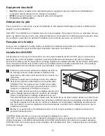
Page 10: ...re pour aide dans ce type d installation Enlevez la radio d usine existante du tableau de bord ou du montage console central Mettez le mat riel et les querres de c t comme cela peut servir monter la n...

Page 11: ...la voiture Apr s avoir termin les branchements de c blage allumez l appareil pour confi rmer l op ration le commutateur d allumage doit tre allum Si l appareil ne fonctionne pas rev rifi ez tout le c...

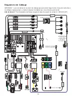
Page 12: ...FRONT L REAR L FRONT R FILTRE FUSIBLE 20A BLEU VERT JAUNE ROSE BRAKE BLEU BLANC BLEU P CONT ANT CONT ANT CONT JAUNE BLEU ROUGE ROUGE BLANC ROUGE ROUGE BLANC JAUNE FRONT L FRONT R REAR L REAR R SUBWOO...

Page 13: ...R 18 AWG 1 02 16 18 AWG 1 02 1 29 For instructions in English see page 1 Para obtener instrucciones en Espanol dirijase a la pagina 5 Pour des instructions en Francais referez vous a la page 9 17 EJEC...

Page 14: ...14 NAV102 BTM10 Bluetooth VM9224R 20 ISO DIN 2 0 DIN Toyota Nissan Mitsubishi Isuzu Hyundai Honda Car Audio M5X6 ISO 1 1 2 3 4 EJE CT MUTE...

Page 15: ...15 a b 12 c M5x6 a b c DVD 30 1 b 1 c 2 5 c 5 2 3 4 1...

Page 16: ...16 ACC iPod C W S PAC SWI PS Bluetooth BTM10 20...

Page 17: ...R 18 AWG 1 02 16 18 AWG 1 02 1 29 For instructions in English see page 1 Para obtener instrucciones en Espanol dirijase a la pagina 5 Pour des instructions en Francais referez vous a la page 9 13 EJEC...

Page 18: ...18 NAV102 BTM10 Bluetooth VM9224R 20 ISO DIN 2 0 DIN Toyota Nissan Mitsubishi Isuzu Hyundai Honda M5X6 ISO 1 1 2 3 4 EJE CT MUTE...

Page 19: ...19 a b 12 c M5x6 a b c DVD 30 1 b 1 c 2 5 c 5 2 3 4 1...

Page 20: ...20 ACC iPod C W S PAC SWI PS Bluetooth Bluetooth 20 Bluetooth...

Reviews: