innoCon 6800 Monitor Manual
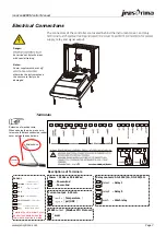
Electrical Connections
The connectors of the controller are located behind the instrument cover, and only
Descriptions of Terminals
Terminals
Page 7
Power
(
24Vdc or 90-260Vac
)
Sensor
Extension of electrical wire:
When opening the wire, make sure
to remove the black conductive rubber
cover outside the central axis.
Terminal 2 and terminal 3 must
be short connected when the
two-wire connection is made
--
Power+End
--
Center axis of
the electrode
--
Cable of sensor
--
Shielded wire
--
Empty feet
--
Connect with the
temperature probe
--
Power-End
RS485
output
(Modbus
RTU Protocol)
Relay contacts
(
AC<250V/5A, DC<30V/5A
)
relay1
-- Relay 1
relay2
-- Relay 2
wash
-- Wash relay
--
(
Temperature
)
--
(
pH/ORP
)
Current output 4-20mA
Shielded wire
Central axis
pH/ORP
REF
AUX
SHIELD
supply, relay and signal output.
Danger:
be carried out by technicians
with special training.
Notes:
Power supply must be cut off
otherwise the instrument and
the sensor are likely to be
damaged.
RS485
www.jensprima.com
Summary of Contents for innoCon 6800P
Page 2: ......

