background image

EC Declaration of Conformity

Jenway Models 6400 and 6405 Spectrophotometers comply with the following European Standards:

EN 50081-1:1992

Electromagnetic compatibility - Generic emission standard

EN 50082-1:1992

Electromagnetic compatibility - Generic immunity standard (Performance
criterion B)

EN 61010-1:1993

Safety requirements for electrical equipment for measurement, control and
laboratory use

Following the provision of:

EMC Directive - 89/336/EEC and Low Voltage Directive - 73/23/EEC

Martyn J. Fall
Managing Director, Jenway Limited,
Gransmore Green, Felsted, Dunmow,
Essex, CM6 3LB, England

640 050/REV B/11-99

47

Summary of Contents for 6405

Page 1: ...MODELS 6400 6405 SPECTROPHOTOMETERS OPERATING MANUAL 640 050 REV B 11 99...

Page 2: ...otometrics 3 3 Spectrum Mode 3 4 Multi Wavelength Mode 3 5 Kinetics Mode 3 6 Quantitation Mode 3 7 Good Practice Guidelines 3 8 SECTION 4 MAINTENANCE General 4 1 Tungsten Halogen Lamp Replacement 4 2...

Page 3: ...On Self Test a Photmetrics Spectrum Multi Wavelength Kinetics and Quantitation Modes b Photometrics Mode c Spectrum Mode d Multi Wavelength Mode please refer to a e Kinetics Mode f Quantitation Mode g...

Page 4: ...n to the detailed instructions specified in this manual 3 The covers on the units should only be removed by personnel who have been trained to avoid the risk of shock 4 References should always be mad...

Page 5: ...resolution can be user adjusted and the resultant scan which appears in real time on the graphics display can be auto scaled to give enhanced visibility Peaks and valleys are labelled with wavelength...

Page 6: ...resolution dependant Resolution 0 001 0 01 0 1 1 Units ppm mg l 1 g l 1 M blank Factor 0 000 to 9999 99 Wavelength Range 320 to 1100nm 6400 190 to 1100nm 6405 Resolution 0 1nm Accuracy 1 0nm Bandwidth...

Page 7: ...e for 115V operation NOTE The unit should be positioned within 1 5 metres of an earthed mains supply VOLTAGE SELECT NOTE When changing the voltage select switch position always ensure the fuse rating...

Page 8: ...u options Up and down arrow keys are also used to select non numeric set up parameters Icons The following icons may appear on the instrument display during operation UV lamp on 6405 only This icon wi...

Page 9: ...d or obstructed at any time 2 Aux SOCKET 7 pin DIN socket Serial communications port for the auxilliary peltier control unit 3 Analog SOCKETS 2 x 4mm pin sockets for analogue output 4 RS232 SOCKET 25...

Page 10: ...quired A failure will be be shown by a X appearing in the box to the side of the parameter under test together with an error message Refer to Section 8 Warning and Error Messages for explanatory notes...

Page 11: ...mpletion of a scan Two scans can be stored A baseline can be manually acquired The instrument can be set to repeat a scan at a user set interval for a user set number of times The instrument can be se...

Page 12: ...n curve of absorbance or transmittance versus concentration to be constructed Sample concentrations are displayed using the relationship of concentration versus absorbance or transmittance derived fro...

Page 13: ...in the in built printer by four lines Used when fitting a new paper roll Clock Allows access to the clock set up menu Time Allows entry of the time 24 hour clock Date Format Allows selection between...

Page 14: ...the wavelength set in this menu When off the deuterium lamp is permanently on Wavelength The wavelength below which the UV lamp will be switched on This is only used if the UV lamp save feature is en...

Page 15: ...key and press MEASURE MODE Select Transmittance Absorbance or Concentration CONCENTRATION SETUP Cal Standard Allows entry of the calibration standard that is calibrated to by pressing the Cal key whe...

Page 16: ...ess to return to the main set up options To select the INSTRUMENT SET UP MENU use the key and press The instrument will enter the menu For details on setting up these parameters refer Section 3 2 NOTE...

Page 17: ...n The scan can be paused and continued or can be aborted Recall Allows a previously saved scan to be recalled onto the display The time and date at which the scan was saved are momentarily displayed R...

Page 18: ...s to confirm the new scan save since the oldest saved scan will be overwritten This message can be suppressed by setting the storing warning messages to off With the storing messages off a scan save w...

Page 19: ...u which allows the instrument to automatically repeat a scan a number of times at a user set time interval Auto Repeat Scan Turns the automatic feature which repeats a scan at a user set time interval...

Page 20: ...option to PAUSE or ABORT the scan On completion the display will update to show the performed scan Performing a Scan Spectrum Mode Post Scan Menu Once a scan has been performed or recalled the follow...

Page 21: ...to MENU The enter key must be pressed to allow access to the other displayed menu options and quit using the cursor Statistics Displays the absorbance or transmittance and wavelengths of the peaks an...

Page 22: ...urements are displayed together with the difference and ratio of the readings at the two wavelengths Multi Wavelength Set up Menu Measure Mode Selects between transmittance or absorbance display of re...

Page 23: ...ress the Cal key The display will momentarily show Calibrating Dark Level Calibrating Light Level and then Reading Sample at the set wavelength This will be repeated for the second wavelength measurem...

Page 24: ...til the total run time has expired For example if the run time is set to 60 seconds readings will be taken every 0 3 seconds It is recommended that set up parameters be reviewed prior to calibration o...

Page 25: ...ge the Y Axis minimum and maximum points to display the scan to it s greatest resolution If set to off then the Y Axis will use the user set maximum and minimum points BestFit Allows access to the lin...

Page 26: ...tart When Level Is When the start on level feature is turned on then the kinetics run time readings will be taken when the measured absorbance is greater or less than the value set by the above level...

Page 27: ...Kinetics Post Measurement Mode Once a kinetics run has been performed the kinetics menu displays the following additional menu option Statistics Displays the first absorbance or transmittance reading...

Page 28: ...andards in non volatile memory A recalled calibration curve cannot be saved If saving a calibration curve will over write an already saved calibration curve then a warning message will be displayed re...

Page 29: ...calibration curve The options are linear interpolation straight lines between calibration points linear regression line of best fit or linear regression through zero line of best fit that passes throu...

Page 30: ...only available when the instrument is fitted with the multi position cell holder Instrument set up parameters should be checked and reset prior to performing calibration and measurement Two to seven c...

Page 31: ...ous results 7 Glass cuvettes should be thoroughly cleaned after use Discard when scratches become evident in polished surfaces 8 Chemical reagents should wherever possible be of high grade quality Con...

Page 32: ...display will extinguish Replacement tungsten halogen lamps are available from the manufacturer or your local distributor CAUTION The following safety precautions should be observed prior to attempting...

Page 33: ...ERIUM LAMP REPLACEMENT MODEL 6405 The deuterium lamp has an extended life of 2000 hours Should the lamp need to be replaced the following procedure should be carried out If the lamp fails during opera...

Page 34: ...ide of the lamp Carefully turn the plate taking care not to strain any of the wires and disconnect the lamp from the white connecting socket Remove the 2 fixing screws from the lamp and place carefull...

Page 35: ...position motorised multi cell changer 645 001 Vacuum Pump 645 100 Vacuum Pump Tubing Kit 035 026 Pour in suck out Cell 646 001 Universal Test Tube Holder 060 331 12mm dia x 75mm Glass Test Tubes Pack...

Page 36: ...h 750 l Glass Cuvette 035 131 Flow through 750 l Quartz Cuvette 035 027 Visible glass 10mm path length Cell 035 028 UV quartz 10mm path length Cell 6405 035 086 Visible glass 20mm path length Cell 035...

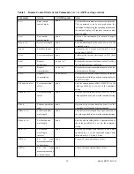
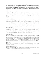
Page 37: ...ation of the instrument at any time and are detailed in Table 1 2 Commands that are terminated by the ACSII carriage return character These commands can be used to remotely control the instrument and...

Page 38: ...bsorbance 100 T Calibrates the current wavelength to 0 T dark calibration Returns the current absorbance value based on the last photometrics calibration Returns the current transmittance based on the...

Page 39: ...hamber Opens the dark shutter to allow light to enter the chamber Allows remote control of active accessories Contact Jenway for details of the accessory control commands Serial Response www w xxx xxx...

Page 40: ...NOTE The Interface Cable Kit Order Code 542 009 can be used to implement the above interconnections 6 3 RECORDER OUTPUT This is available via the 4mm rear panel sockets The level is proportional to th...

Page 41: ...isible spectrum as normal Once the warning message has been cleared the instrument will continue to attempt to strike the deuterium lamp as a deuterium lamp ages it is possible that the time allowed f...

Page 42: ...ble that failure of this mechanism will also cause this error b Photometrics Spectrum Multi Wavelength Kinetics and Quantitation Modes Dark Level Too High This error occurs during a photometrics calib...

Page 43: ...ew Baseline Scan is Executed Before Performing Spectrum Scans This message is displayed on entry into Spectrum mode as a reminder to perform a baseline scan prior to performing sample scans Since the...

Page 44: ...s error is reported when the user selects an invalid region of a kinetics run for the line of best fit For example when the line of best fit end point is set to be less than the line of best fit start...

Page 45: ...ating the calibration The number of standards and standard concentration can be viewed but not changed No Quantitation Data to Save This warning message is displayed when the user attempts to save a c...

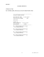
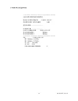
Page 46: ...29 19 11 97 INSTRUMENT ID NUMBER 6400 OPERATOR SAMPLE ID LAST CALIBRATED 15 13 59 19 11 97 WAVELENGTH 345 0nm 001 100 0 T 345 0nm 15 14 33 19 11 97 CELL HOLDER POSITION 0 002 100 2 T 345 0nm 15 56 00...

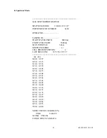
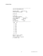
Page 47: ...HOLDER POSITION 4 LAST BASE LINE 14 51 56 19 11 97 nm Abs 600 0 0 297 605 0 0 313 610 0 0 332 615 0 0 359 620 0 0 402 625 0 0 453 630 0 0 508 635 0 0 552 640 0 0 568 645 0 0 544 650 0 0 485 655 0 0 40...

Page 48: ...ID NUMBER 6400 OPERATOR SAMPLE ID LAST CALIBRATED 16 02 16 19 11 97 WAVELENGTH 1 500 0nm WAVELENGTH 2 600 0nm 001 16 02 24 19 11 97 W1 500 0nm 1 417Abs W2 600 0nm 1 551Abs A1 A2 0 134Abs A1 A2 0 913...

Page 49: ...OSITION 6 LAST CALIBRATED 11 12 26 14 11 97 WAVELENGTH 600 0nm FACTOR 100 000 RUN TIME SEC 10 SEC TIME Abs 0 1 874 1 1 870 2 1 867 3 1 852 4 1 842 5 1 824 6 1 801 7 1 805 8 1 800 9 1 796 10 1 792 INIT...

Page 50: ...DS USED 5 CAL STANDARD 1 10 000 74 8 T CAL STANDARD 2 20 000 66 3 T CAL STANDARD 3 30 000 49 1 T CAL STANDARD 4 40 000 28 1 T CAL STANDARD 5 50 000 5 4 T LINEAR INTERPOLATION CAL STANDARD T 10 000 74...

Page 51: ...rd EN 50082 1 1992 Electromagnetic compatibility Generic immunity standard Performance criterion B EN 61010 1 1993 Safety requirements for electrical equipment for measurement control and laboratory u...

Page 52: ...g the details below UK Office Keison Products P O Box 2124 Chelmsford Essex CM1 3UP England Tel 44 0 330 088 0560 Fax 44 0 1245 808399 Email sales keison co uk Please note Product designs and specific...

Reviews: