5-110
TMPM5200-2
2.
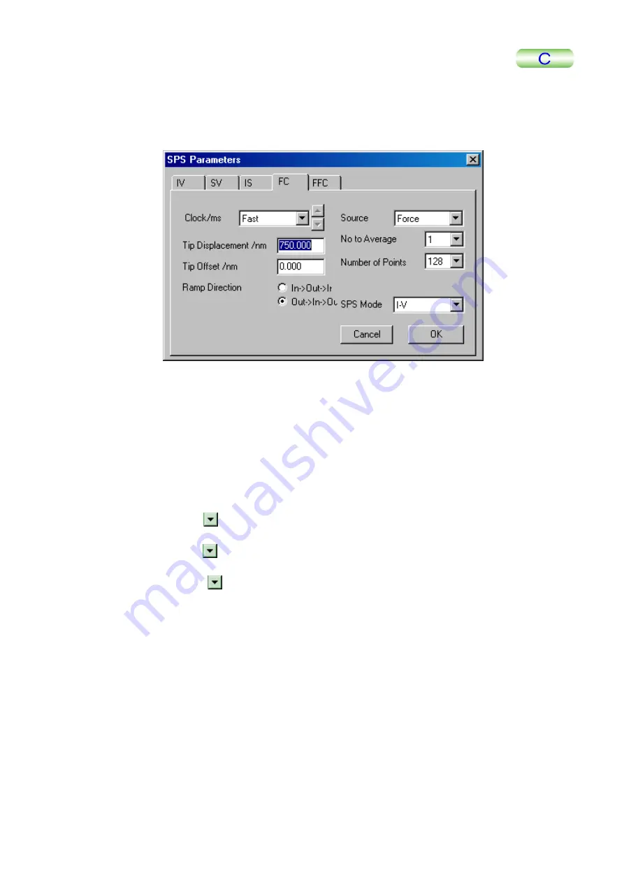
Click on the SPS button in the main menu.
The SPS Parameters window will be displayed.
3.
Click on the FC tab.
4.
D
enter the maximum value of the scanner Z scanning range using the key-
board.
In practice, even if you en
anning range, the
software automatically calcu
nd indicates the maximum possible value (half
distance of the Z scanning range as the tip displaces in the positive and negative
directions).
5.
Double-click on the Tip Offset/nm input box and enter 0 using the keyboard.
6.
Set Ramp Direction to Out
→
In
→
Out.
7.
Click on the
ouble-click on the Tip Displacement/nm input box on the FC window and
tered a value exceeding the scanner Z sc
lates a
button in the No to Average selection box and select 1 from
the pull-down menu.
8.
Click on the
button in the Source selection box and select Force from the
ull-down menu.
p
9
Click on the
.
button in the SPS Mode selection box and select Force
1
Curve from the pull-down menu.
0.
Click on the Repeat button on the Advanced tab window.
The Force Curve will be measured and displayed on the Display Window.


