6.8.6 Drift
Correction
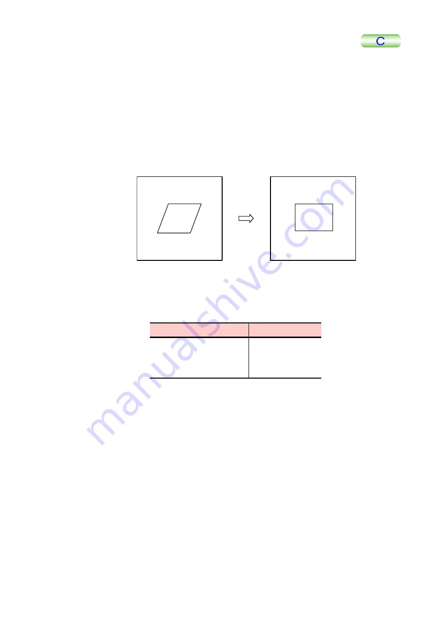
Corrects the distortion (drift) of the current image.
1.
Click on Geometry in the main menu; then select Drift Correction in the
pull-down menu.
A cross cursor “+” appears on the image.
2.
Specify an image distortion at 3 corners of a parallelogram–the starting point
(1/3), the 1st vector endpoint (2/3), and the 2nd vector endpoint (3/3)–in
accordance with the guidance displayed on the window.
A corrected image is displayed.
Drift
Correction
Current image
Corrected image
1/3
2/3
3/3
If the parallelogram used for designation is small, the corrected image is also small.
The size relation between the designated parallelogram frame and the converted
square frame is as follow:
Designated parallelogram
Corrected image
Less than 128
×
128
128
×
128 pixels
Less than 256
×
256
256
×
256 pixels
256
×
256 or more
512
×
512 pixels
6.8.7 Average
Unit
Cell
The entire image is reconstructed with a designated unit cell.
1.
Click on Geometry in the main menu; then select Average Unit Cell in the
pull-down menu.
A cross cursor “+” appears on the image.
2.
Designate 3 corners of a parallelogram as a unit cell.
Designate the starting point (1/3), the 1st vector endpoint (2/3), and the 2nd vector
endpoint (3/3) in accordance with the directions displayed on the window. This
operation designates the shape of the unit cell of the mesh.
The message “Enter integral factor to scale vector down by” is displayed on the
window.
TMPM5200-2
6-67


