MAGPRO 35
7 of 10
We recommend inspecting all the items delivered for complete-
ness and any transport damage. Complaints are generally only
accepted if they are registered on the day they are received.
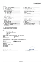
Assembly of coolant tank
First attach clear tube to the bottom of the coolant tank. To do
this, first loosen the nut and slide nut onto the tube. Then slide
tube onto the nipple. Then tighten the nut.
Slide tank hanger over the screw on the upper right hand side of
slide and tighten.
Finally insert the other end of the tube into the connector in the
gearbox. Just directly push in to install. (To remove, first firmly
push the collar of the connector and pull the tube out.)
Cutting coolant fluid is always required when using annular
cutters. Open tank cover and fill. Check coolant fluid level often.
Keep coolant tap closed when not in use. Empty coolant tank
when returning the machine to the carry case.
Chip guard must be used.
To attach the chip guard,
use the sup-plied butterfly bolts to bolt to the magnet. It
is not necessary to remove guard to clean chips. Simply
raise guard to its upper position.
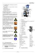
Warning
Safety chain must be used.
Loop chain around the
work piece and feed through the machines handle and
clip in place. MOUNTING ANNULAR CUTTERS:
CAUTION: Never use a cutting tool, which is larger than
the maximum rated capacity of the machine.
Warning
5.4
SPECIAL INSTRUCTIONS FOR
AUTO-REVERSE TAPPING
MODELS
THIS MACHINE IS THE FIRST OF ITS KIND SO
SPECIAL CARE MUST BE PAID TO THE
OPERATING INSTRUCTIONS BELOW TO
UNDERSTAND ITS TAPPING FUNCTION.
CAUTION: Before beginning tapping ensure that
the hole is the correct size for the tap. An under-
size hole will cause the tap to jam causing a
hazardous situation.
CAUTION: When tapping a blind hole always
correctly use the travel limiter stop to ensure
that there is enough clearance so that you do
not bottom-out the tap. Bottoming will cause
the tap to jam, causing a hazardous situation.
CAUTION: Never attempt to tap with the gear-
box selector in standard drilling mode.
The much higher speed of the standard drilling
mode will damage the tap and cause a hazardous
situation .
COOLING:
The automatic through the spindle cooling
function is only effective when using annular cutters.
When tapping or using twist drills, cutting oil must be
added manually.
5.4.1 Setting up for tapping
CAUTION: Never use a cutting tool which is larger
than the maximum rated capacity of the machine.
CAUTION:: Always follow the tap manufacturer ’ s
recommendation for selecting the correct size hole
for tapping.
CAUTION: Never attempt to change gears on a
running machine! Only change gears when the
Caution
machine is at rest.
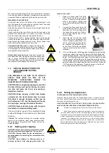
1.
Select the correct sized Tap Collet
Arbor for the tap which you intend
to use. If there is already another
arbor in the machine, simply push
up on the Quick-Release Collar and
remove.
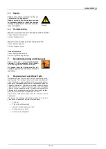
2.
To insert the Arbor, push up on the
Quick-Release Collar (1) and insert
the Arbor (2). Turn the Arbor until
the tangs line up and the Collar is
able to close. Ensure that it is se-
curely in place.
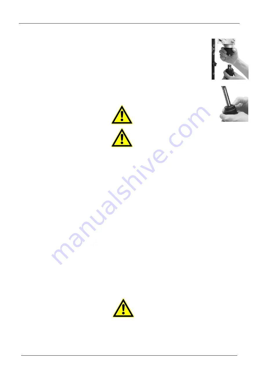
3.
Insert the tap into the Tap Collet
Arbor. Push up on the tap and turn
it until it snaps in place. When it is
time to remove the tap from the Ar-
bor, depress the Release Ring (3)
on the Arbor. (Catch the tap so that
it does not fall on the floor when it
releases.)
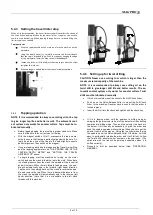
4.
If it is in drilling mode, shift the gearbox to tapping mode by swing-
ing the gear selector tab out of the detent slot then shifting down-
wards into tapping mode. Then pop the selector tab back into the
detent . It will sometimes be necessary to turn the spindle by hand
a little to get it to shift all the way. Only grab the arbor when turn-
ing the spindle, never the quick-release collar. Otherwise, it will be
easy to accidentally release the arbor and it will fall out. Follow the
“TAP” symbol on the gear case. (The small arrow on the tab will
be pointing upwards when it is shifted correctly).
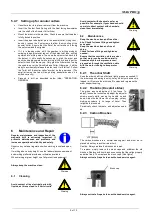
5.4.2 Setting the depth meter
THE PROPER USE OF THE TAPPING DEPTH METER:
Whenever tapping blind holes, the Tapping Depth Meter in conjunction with
the Travel Limiter Stop must be used for ensuring the prevention of possible
damage to the gearbox and the tap.
ALWAYS ENSURE THAT THE HOLE ISN’T OVER TAPPED. THE HOLE’S DEPTH
MUST BE MUST BE LONGER THAN THE NEEDED THREADING DEPTH!!
•
Pre-place the tap against the work piece. To zero-in the needle.
•
While keeping the tap against the workpiece, adjust the pointer to
the 4mm datum position on the left-hand tapping scale. (The tapping
function has an extra 4mm movement when the crank handle is released,
a 4mm pre-adjustment has been made on the scale. Therefore, when
"zeroing-in" the tapping scale, the 4mm mark is the effective datum
point. A minimum depth of 5mm can be tapped and a maximum of
40mm). Now that you have the depth scal e calibrated, you may use the
meter reading to set the Travel Limiter Stop.
1
2
3

