The POTC Menu System
B-6
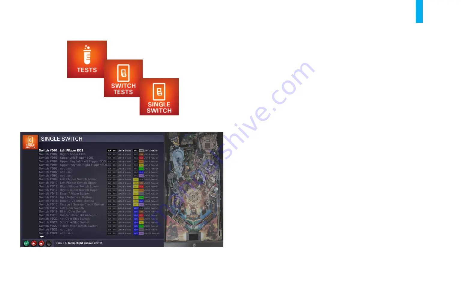
Single Switch Test
When you enter the
Single Switch Test
, the LCD monitor will display the screen shown in figure B6.
The entire list of dedicated and matrixed switches is shown alongside a window highlighting the
location/state of the currently selected switch on the game’s playfield (at right in figure B6). The
switch is displayed as a small, blinking square; the color of the square represents its current state.
An active switch, regardless of its type, is displayed as a bright green square. An inactive opto
switch is displayed as a light tan (if normally unblocked) or dark tan (if normally blocked) square;
any other inactive switch is displayed as a bright blue (if normally open) or navy blue (if normally
closed) square. A bad switch (a switch that has been inactive for approximately 60 balls played) is
displayed as a red square. Unused positions in the matrix are not displayed in the playfield window.
All switch driver (column) and return (row) numbers are shown, along with corresponding wire
colors and I/O Board connector/pin numbers.
You can scroll through the list of matrixed switches, using the
Up/+
and
Down/-
buttons, and select
any switch to test. You can then repeatedly open or close the selected switch, observing the results
in the playfield window. The game also provides an audible response each time the state of the
switch changes. Note: When adjusting a switch, the best method for testing it is to roll a pinball
over it, through it or into it.
To exit the
Single Switch Test
at any time, press the
Back/Escape
button.
Figure B6. Single Switch Test screen.
Summary of Contents for Pirates of the Caribbean
Page 2: ......
Page 13: ...Game Assembly Setup A 1 Game Assembly Setup Section A...
Page 37: ...The POTC Menu System B 1 The POTC Menu System Section B...
Page 93: ...Game Parts Information C 1 Game Parts Information Section C...
Page 98: ...Game Parts Information C 6 1 2 3 4 5 6 7 8 9 14 12 16 11 10 13 15...
Page 112: ...Game Parts Information C 20 1 2 5 9 3 13 6 10 4 15 16 11 8 7 12 18 17 14 12 18 17 14...
Page 114: ...Game Parts Information C 22 2 4 12 3 16 17 10 11 5 7 6 18 8 14 9 13 1 15 8...
Page 146: ...Game Parts Information C 54 7 14 1 4 9 11 3 2 5 8 8 10 10 12 13 15 16 16 17 6...
Page 166: ...Game Parts Information C 74 15 1 25 2 3 4 5 6 9 10 11 12 13 14 19 17 18 20 21 26 27 28...
Page 168: ...Game Parts Information C 76 1 2 3 4 5 6 9 10 11 12 13 14 15 25 17 18 20 19 26 21 27 28...
Page 170: ...Game Parts Information C 78 49 51 50 55 56 41 42 43 44 45 46 46 46 47 48 76 77 46...
Page 172: ...Game Parts Information C 80 49 51 50 55 56 41 42 43 44 45 46 46 46 47 48 76 77...
Page 200: ...Game Parts Information C 108 79 65 69 70 71 72 73 74 75 76 77 78 81 80 82 83 84 85 86 87 88...
Page 202: ...Game Parts Information C 110 9 10 12 13 14 15 66 67 68 9 10 12 15 13 14 66 67 68...
Page 208: ...Game Parts Information C 116 32 79 65 69 70 71 72 75 74 73 76 77 78 80 81 82 83 84 85 86 87 88...
Page 212: ...Game Parts Information C 120 23 16 4 6 15 12 10 9 5 2 3 17 13 18 7 22 8 21 20 19 27...
Page 214: ...Game Parts Information C 122 1 14 25 24 11 26 26 26 26 34 32 32 32 30 31 31...
Page 216: ...Game Parts Information C 124 8 3 4 5 1 2 6 7...
Page 220: ...Game Parts Information C 128 0 1 14 2 3 5 4 11 7 6 9 10 12 15...
Page 222: ...Game Parts Information C 130 13 4 5 5 4 4 3 1 2 2 1 7 6 6 6 6 6 6 6 6 6 6 6 6 8 8 8 13 13...
Page 230: ...Game Parts Information C 138 1 2 3 4 5 10 9 8...
Page 232: ...Game Parts Information C 140 1 1 1 2 2 3 3 4 5 8 7 7 7 7 7 7...
Page 234: ...Game Parts Information C 142 1 1 1 1 1 1 1 1 1 1...
Page 248: ...Game Parts Information C 156...
Page 249: ...Reference Diagrams Schematics D 1 Reference Diagrams Schematics Section D...
Page 302: ...Reference Diagrams Schematics D 54...
Page 308: ...Reference Diagrams Schematics D 60...
Page 337: ...Reference Diagrams Schematics D 89 1 Fuse Locations Bottom of Cabinet 4 2 3 In Backbox...
Page 343: ...Game Service Troubleshooting E 1 Game Service Troubleshooting Section E...
Page 353: ...Appendices...
Page 358: ......


