12 | Operating Manual GW 702 | Assembly and Installation
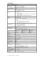
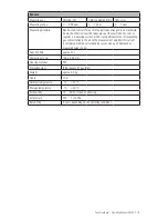
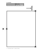
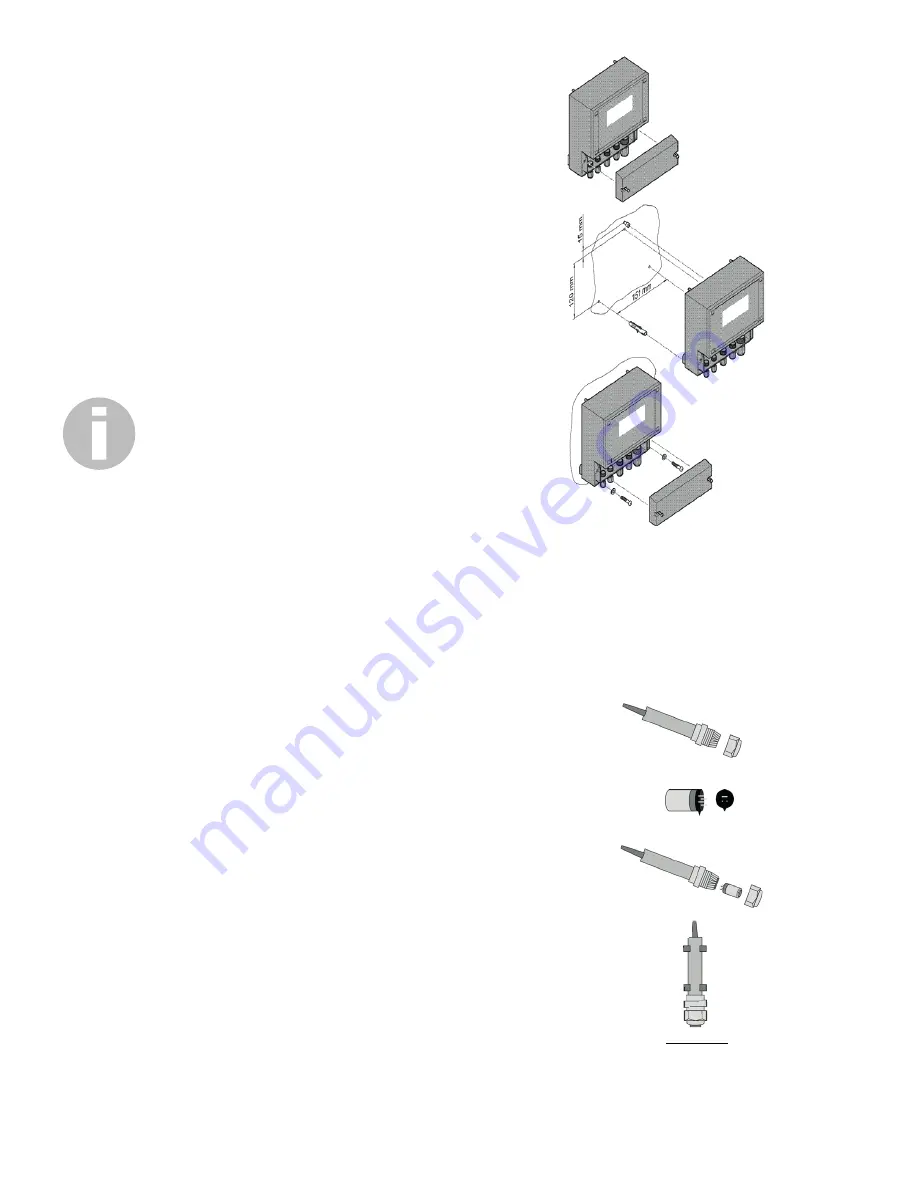
• First, remove the terminal cover.
• Prepare three drill holes (max. M5).
• Take into account at the top hole, that you can suspend the device
or push it under.
• To suspend it, set the top hole 120 mm above the two lower
holes.
• To push it under, the distance must be 135 mm.
• In both cases the screw must protrude at least 3 mm.
• Suspend the device on the top screw or push it underneath.
• Fix it with the two lower screws.
• Re-attach the terminal cover or proceed directly to the connec-
tions.
6.2 Sensor
• Up to 2 sensors can be connected to the measurement amplifier
GW 702.
• The connection of a sensor takes place by means of the shielded
3-wire cable attached to the sensor holder.
IMPORTANT!
The length of the cable must neither be extended nor shortened.
• All input and output wires and cables must be shielded. The
shielding must be applied on one side only.
• The gas inlet of the sensor must be kept clear of dust and
contamination.
• The wall mounting is carried out with the sensor opening facing
down, close to the ground (at a height of approx. 30 cm).
• During assembly make sure that the sensor remains accessible for
maintenance work.
• Keep a minimum distance of 10 cm between the sensor opening
and other fixtures.
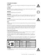
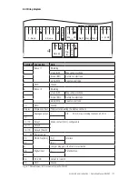
a
Unscrew the O-ring of the sensor holder.
b
Take the sensor element from the separate packaging and remove
the transport protection. (shorting jumper).
c
Fit the sensor element into the sensor holder without force. Note,
that the correct seating position is indicated by a groove. Ensure that the
connecting pins are not bent. Check the correct seating of the seal and
screw on the union nut again.
d
Mount the completed sensor perpendicular with two mounting
brackets, with the sensor element facing down, about 30 cm above the
ground. Ensure that the sensor is not subjected to any strong wind, heat
or direct sunlight and that the sensor element can not get wet at any
time.
a
b
c
d

