background image

Lutz-Jesco GmbH 

Am Bostelberge 19
30900 Wedemark
Germany

Telephone: +49 5130 5802-0
Fax: +49 5130 580268
info@lutz-jesco.com
www.lutz-jesco.com/de

24 hour hotline: +49 5130 580 280

Austria

Lutz-Jesco GmbH 

Aredstraße 7/2
2544 Leobersdorf
Austria

Telephone: +43 2256 62180
Fax: +43 2256 6218062
info@lutz-jesco.at
www.lutz-jesco.at

Netherlands

Lutz-Jesco Nederland B.V.

Nijverheidstraat 14 C
2984 AH Ridderkerk
Netherlands

Telephone: +31 180 499460
Fax: +31 180 497516
info@lutz-jesco.nl
www.lutz-jesco.nl

USA

Lutz-JESCO America Corp.  

55 Bermar Park
Rochester, NY 14624
USA

Telephone: +1 585 426-0990
Fax: +1 585 426-4025
mail@jescoamerica.com
www.jescoamerica.com

East Asia

Lutz-Jesco
East Asia Sdn Bhd

Taman Perindustrian Jaya
47200 Petaling Jaya
Malaysia

Telephone: +603 78454812
Fax: +603 78458413
info@lutz-jescoasia.com
www.lutz-jescoasia.com

Middle East

Lutz-Jesco Middle East FZE

P.O. Box 9614
SAIF-Free Zone Center
Sharjah
UAE

Telephone: +971 6 5572205
Fax: +971 6 5572230
info@jescome.com
www.jescome.com

Order No. BA-23607-02-V05
Subject to technical changes
© Lutz-Jesco GmbH 04.2014
Printed in Germany 

Hungary

Lutz-Jesco Üzletág 

Vasvári P. u. 9.
9024 Györ
Hungary

Telephone: +36 96 523046
Fax: +36 96 523047
info@lutz-jesco.hu
www.lutz-jesco.hu

Great Britain

Lutz-Jesco (GB) Ltd. 

Gateway Estate
West Midlands Freeport
Birmingham B26 3QD
Great Britain

Telephone: +44 121 782 2662
Fax: +44 121 782 2680
info@lutz-jesco.co.uk
www.lutz-jesco.co.uk

*BA-23607-02*

certified

DE

KRA

 Certificatio

n

ISO 9001:2008

ISO 14001:2004

Quality Management

ISO 9001:2008

Environmental Management

ISO 14001:2004

Voluntary participation in regular 
monitoring

Summary of Contents for GW 702

Page 1: ...ning Device for Chlorine Gas Chlorine Dioxide and Ozone EN 02 Operating Manual Read this operating manual before using the equipment To be retained for future reference Dosing Liquids Conveying Gases Control Systems ...

Page 2: ...arameters 15 7 2 Menu Overview 16 7 3 Code 16 7 4 Language 16 8 Configuration 17 8 1 Sensors 17 8 2 Sensor Slope 18 8 3 Sensor Test 18 9 Operating Modes 19 10 Relays 20 10 1 Action in the event of an alarm or fault 20 10 2 Configuration 21 10 3 Relay Test 21 11 Analogue Output and Interface 22 11 1 Analogue output 22 11 2 Interface 22 12 Check function 22 13 Maintenance 23 13 1 Replacing the senso...

Page 3: ... in damage to the device and endanger its operation IMPORTANT This refers to additional information to facilitate operation and ensure the smooth running of the equipment Notices attached directly to the unit such as e g cable markings must definitely be observed and kept in completely legible condition 1 3 Personnel qualifications and training The personnel employed for operation maintenance insp...

Page 4: ...ficial disposal of process materials as well as replacement parts must be ensured Legal requirements must be observed Risks from electric power must be excluded for further details refer to the VDE1 regulations and the requirements of the local public utilities as well as section 1 4 1 VDE Association of German Electrical Engineers 1 8 Safety instructions for inspection maintenance and installatio...

Page 5: ...note immediately If there are any discrepancies determine the cause The scope of delivery includes Measurement amplifier GW 702 1 or 2 sensor elements depending on version 1 or 2 sensor holders incl 10 m cable depending on version 2 or 4 pipe clamps d25 depending on version Operating Manual 2 3 Start up procedure Reading the operating manual Assembly and installation section 6 Checking the functio...

Page 6: ...alarm thresholds set have been exceeded alarm conditions are displayed or relays switched to notify the relevant persons 3 1 Measurement amplifier GW 702 The measurement amplifier GW 702 is the central control unit and is installed where it can be accessed by operators It allows measurements to be checked and alarm thresholds set It evaluates the electrical behaviour of the sensor The digital disp...

Page 7: ...Dimensioned drawings Operating Manual GW 702 7 4 Dimensioned drawings Fig 4 1 Measurement amplifier GW 702 Fig 4 2 Sensor holder 380 380 210 Fig 4 3 Power supply backup system accessory ...

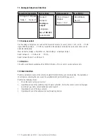
Page 8: ... fixed assigned sensor 1 and sensor 2 Relay 3 alarm freely assignable sensor 1 and or sensor 2 Analogue output 0 4 20 mA galvanically isolated max working resistance 500 Ω to be assigned sensor 1 or sensor 2 Number of sensors Max 2 Alarm thresholds 2 limits pre configured freely adjustable Chlorine Cl2 Chlorine dioxide ClO2 Ozone O3 Limit 1 2 ppm 0 2 ppm 0 2 ppm Limit 2 9 5 ppm 1 ppm 1 ppm Digital...

Page 9: ...ent which is proportional to the corresponding gas concentration in the air In the measurement amplifier this current is calculated with the corresponding sensor slope and displayed as measured value in ppm Reaction time approx 30 s Dimensions L x ø 135 x ø 33 mm Housing material PVC Protection class IP 54 except for gas inlet Weight approx 0 2 kg Cable 10 m Ambient temperature 10 40 C Storage tem...

Page 10: ...z Output rated current 2 2 A Protection Overload Full discharge Short circuit Overtemperature Charge time 8 h Battery 12 V DC 7 Ah maintenance free 3 5 years service life Interface USB RS 232 Ambient temperature 0 45 C Storage temperature 0 45 C Air humidity 0 90 rH non condensing Housing Steel sheet powder coated lockable Dimensions W x H x D 380 x 380 x 210 mm Protection class IP 66 Weight appro...

Page 11: ... cables must be adhered to with regard to the sensor used When measuring ensure that the plug connections are clean and dry and that the lines do not become brittle due to sharp buckling The shielded cables normally used for such measuring lines must be of the quality specified 6 1 Measurement amplifier GW 702 The electrical installation for the gas warning device must contain a separating device ...

Page 12: ...ust be applied on one side only The gas inlet of the sensor must be kept clear of dust and contamination The wall mounting is carried out with the sensor opening facing down close to the ground at a height of approx 30 cm During assembly make sure that the sensor remains accessible for maintenance work Keep a minimum distance of 10 cm between the sensor opening and other fixtures a Unscrew the O r...

Page 13: ...e 5 GND Ground 6 Sensor 2 Shielding 7 green GN Measuring electrode 8 brown BN Reference electrode 9 white WH Counter electrode 10 GND Ground Display Display contrast Trimmer for adapting the display contrast 11 Analogue output 0 4 20 mA max working resistance 500 Ω 12 14 15 Relay 1 Make contact N O configurable 16 17 Relay 2 18 19 Relay 3 Alarm 20 22 Power supply 23 RS 485 option A Interface 24 B ...

Page 14: ...14 Operating Manual GW 702 Assembly and Installation 6 4 Drill template Width x height Measurement amplifier GW 702 151 x 120 15 mm ...

Page 15: ... value display at any time 7 1 Setting parameters 1 When selecting a parameter the current setting is displayed 2 Switch to the next alternative by pressing the key 3 When you have paged through all alternatives with a renewed press of the key the original setting is displayed again Selection of alternatives Often for a parameter you must only select between various alternatives For this you only ...

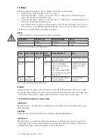
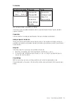
Page 16: ...c settings Service 0 09 ppm 0 01 ppm Sens 1 Sens 2 Preselect M1 Preselect M2 Enter password Sensor test Basic settings Service Sensor 1 Sensor 2 Analogue output Language No of RS 485 Select Alarm Product Info Analogue Inputs Relay Test Erase Settings In the main menu you will find all functions that are used regularly The menu Basic Settings contains the parameters that are set during start up In ...

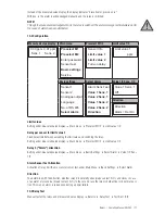
Page 17: ...tion the slope is printed on the housing of every sensor This value is to be set in the main menu The function of the sensor is controlled automatically and electronically at specified intervals In addition a sensor test can be triggered manually at any time 8 1 Sensors Selection options for Sensor 1 and Sensor 2 Selection Sensor for measuring gas No sensor connected Chlorine Chlorine gas Cl2 Chlo...

Page 18: ...ens 1 Value 1 Sens 2 Value 2 Sens 2 Direction Alarm Sens Test On Automatic Sensor Test The device automatically checks electronically the signal of the sensor The time interval between two suc cessive tests can be specified in hours in the main menu under Sensor Test All switching functions of the sensor are disabled during the approx 5 sec test In the display the message Sensor Test is displayed ...

Page 19: ...f the measurement amplifier GW 702 takes place automatically The status is not indi cated in the display The measured values of the sensors are visible over the menu Service see section 13 Sensor test The device automatically checks electronically the signal of the sensor The time interval between two suc cessive tests can be specified in hours in the main menu under Sensor Test see section 8 3 Al...

Page 20: ...wl edged immediately Optical signal generator Relay 2 2 Yes Can be acknowledged immediately externally via digital input Can only be acknowledged manually when the level falls below limit 2 Sprinkler with acknowl edgement via door contact Relay 3 Alarm 1 or 2 Standard 2 No Can be manually acknowl edged immediately Acoustic signal generator Tab 10 2 GW 702 measurement amplifier relays Example If re...

Page 21: ...e 2 Sens 2 Direction Value 1 Sens 1 Off Direction Direction Alarm Rel On Limit values Setting under measured value display Main menu Preselect M1 2 Limit value 1 2 Delay per sensor for limit value 2 Fixed delay time between exceeding the limit value and switching the relay Setting under measured value display Main menu Preselect M1 2 Limit value 1 2 Relay 3 Alarm allocation Setting under measured ...

Page 22: ... display Main Menu Basic Settings Analogue Output Select between 0 20 mA and 4 20 mA Select between Sensor 1 and Sensor 2 11 2 Interface The units are optionally available with an RS 485 interface This is used for service purposes only 12 Check function Perform operational checks of the sensor and alarm threshold limits upon commissioning The operational check involves checking the sensor and the ...

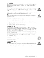
Page 23: ...with test gas with a concentration above limit value 2 Operational check of the relay contacts Operational check of the optical and acoustic warning devices 13 1 Replacing the sensor The sensor element in the sensor holder is subject to ageing and wear the extent of which depends largely on the prevailing conditions at the place of application For this reason the sensor element is excluded from th...

Page 24: ... fuse is included in the scope of supply It is located in the terminal cover 1 To replace the fuse unscrew and lift up the front of the device The fuse is located in the lower right area It is held in place on with a bayonet catch 2 Turn the catch anticlockwise until the fuse jumps out 3 Replace it with the spare fuse and fix it in place by turning the catch clockwise 4 Replace the front of the de...

Page 25: ...puts of the Sensors Here you see which data the device receives from the sensors This raw data is not influenced by com pensations and calibration and provides important information when problems arise with measurement or device operation Relay Test In the menu Relay Test every relay can be switched off manually 1 Select the corresponding relay in the menu Relay Test with the keys and 2 To switch ...

Page 26: ...W 702 chlorine gas 78659 Sensor element for GW 702 chlorine dioxide 78673 Sensor element for GW 702 ozone Device revision This operating manual applies to the following devices Device and model Revision status Device ID S N GW 702 11 2009 8534 271B0000203 It contains all the technical information required for installation start up and maintenance Should you have any questions or require further in...

Page 27: ...llation 11 Interface 22 K Keys 15 L Language 16 Limit value 20 M Maintenance 23 Measurement amplifier 6 Measuring gas 6 Measuring principle 9 Measuring range 9 Menu overview 16 O Operation 15 P Part numbers 5 Power consumption 8 Power supply backup system 6 Protective circuit 11 R Relay 20 Relay Test 25 Replacing the sensor 23 S Safety instructions 3 Scope of delivery 5 Self locking 20 Sensors 6 S...

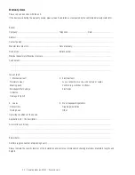
Page 28: ...ls Type of fault 1 Mechanical fault 2 Electrical fault Premature wear Loose connections such as connectors or cables Wearing parts Controls e g switches buttons Breakage other damage Electronics Corrosion Damage in transit 3 Leaks 4 No or inadequate operation Connections Diaphragm defective Dosing head Other Operating conditions of the device Application site site description Accessories used if a...

Page 29: ...0 Wedemark bevestigt dat het volgende genoemde apparaat in de door ons in de handel gebrachte uitvoering voldoet aan de eis van en in overeenstemming is met de EU richtlijnen de EU veiligheidsstandaard en de voor het product specifieke standaard Bij een niet met ons afgestemde verandering aan het apparaat verliest deze verklaring haar geldigheid HU EG EK Egyezőségi nyilatkozat A Lutz Jesco GmbH Am...

Page 30: ...30 Operating Manual GW 702 Notes Notes ...

Page 31: ...Notes Operating Manual GW 702 31 Notes ...

Page 32: ...ian Jaya 47200 Petaling Jaya Malaysia Telephone 603 78454812 Fax 603 78458413 info lutz jescoasia com www lutz jescoasia com Middle East Lutz Jesco Middle East FZE P O Box 9614 SAIF Free Zone Center Sharjah UAE Telephone 971 6 5572205 Fax 971 6 5572230 info jescome com www jescome com Order No BA 23607 02 V05 Subject to technical changes Lutz Jesco GmbH 04 2014 Printed in Germany Hungary Lutz Jesc...

Reviews: