25
CHUCKS AND CHUCK MOUNTING
When fitting chucks or faceplates, ensure that the spindle
and chuck tapers are scrupulously clean and that all
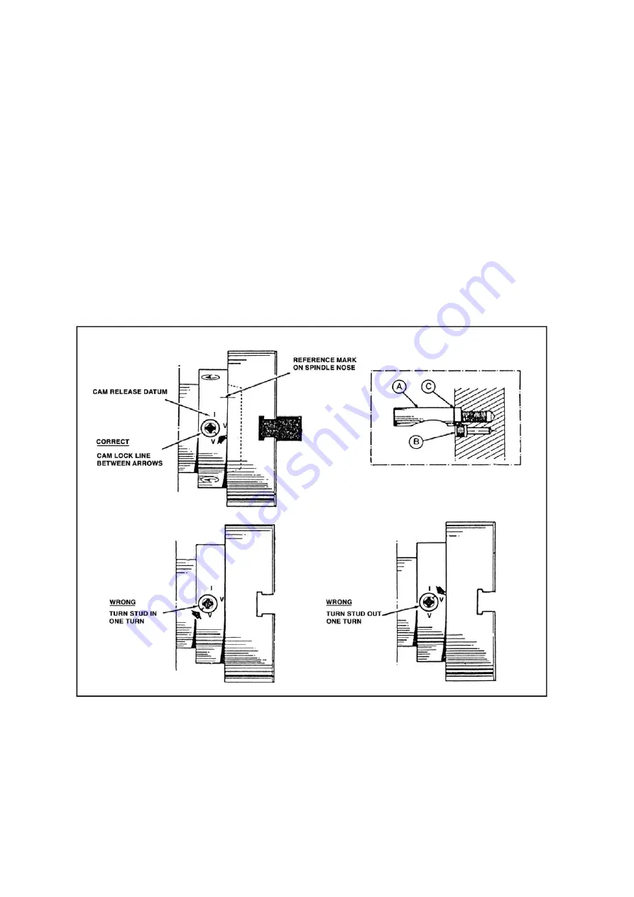
cams lock in the correct positions; see Fig.7. It may be
necessary when mounting a new chuck to re-set the
camlock studs (A). To do this, remove the cap-head
locking screws (B) and set each stud so that the scribed
ring (C) is flush with the rear face of the chuck-with the
slot lining up with the locking screw hole (see inset, Fig.7.)
Now mount the chuck or faceplate on the spindle nose
and tighten the three cams in turn. When fully tightened,
the cam lock line on each cam should be between the
two V marks on the spindle nose.
If any of the cams do not tighten fully within these limit
marks, remove the chuck or faceplate and readjust the
stud as indicated in the illustration. Fit and tighten the
locking screw (B) at each stud before remounting the
chuck for work.
A reference mark should be made on each correctly fitted
chuck or faceplate to coincide with the reference mark
scribed on the spindle nose.
This will assist subsequent remounting.
DO NOT INTERCHANGE CHUCKS OR FACE PLATES
BETWEEN LATHES WITHOUT CHECKING FOR
CORRECT CAM LOCKING.
WARNING
Chuck should be CE approval of EN 1550, the relevant
required markings in it. Take careful note of speed
limitations when using chucks and faceplates.
NOTE:
1. Balance requirements on workpiece clamping
device shall be followed: Workpiece clamping
devices shall only be modified in accordance
with the clamping device manufacturer’s
recommendation.
2. Shall be provided that machining unbalanced
workpiece may create an ejection hazard and
that means of minimizing the risk is counter balancing or
machining at reduced speed.
3. The machine is not allowed to machine the aluminum or
magnesium alloy, which can cause additional, hazards e.g.
fire and explosion or noxious dust.
4. Take careful note of speed limliations when using
faceplates; 10 in. (250mm) faceplates should not be run at
speeds greater than 1200 RPM.
Fig.7

