background image

INSTALLING YOUR STOCK GUIDES TO A ROUTER TABLE OR TABLE SAW 

WITH AN UP TOP 1/4" T-SLOT

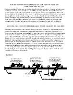
There is an additional set of eight (8) counter bored holes for use with the ¼”-20 Low Head Cap Screws 

and the ¼”-20 square nuts,  but only one row will line up with your T-Slot.  We have included four 

screws and four square nuts for use with these.  Because there are two rows of these holes, it does not 

matter which side faces the front of your fence.  To install on a top mounted T-Slot, slide the four square 

nuts roughly into position and then using the 1/8” hex key, screw in the four ¼”-20 Low Head Cap 

Screws through the track and into the nuts.  Slide the track for best placement on both sides of your 

router bit or table saw blade and tighten these screws.  Loosen the track knobs on each stock guide 

enough to allow it to slide onto the track. Position the stock guide and re-tighten the track knobs.

ADJUSTING THE LENGTH OF THE ROLLER ARM ON YOUR CLEAR-CUT STOCK GUIDES

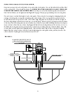
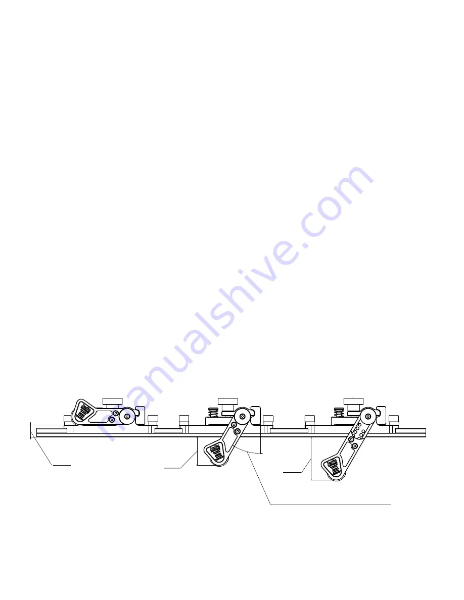
The roller arm is adjustable to five different positions and can be extended 1.3" from the fully retracted 

position it is shipped in.  On the most common table saw fences the fully retracted position as it is 

shipped is the correct setting.  On some higher fences or on a router table fence which is typically higher 

than a table saw fence the stock guides need to be extended.  The ideal position for cutting with your 

stock guides is for the roller arm to be at approximately a 30 degree angle from vertical or greater.  (See 

Figure #3

)   They will work at less of an angle but will apply more lifting force to the fence in the case of 

kick back.  Once the length of the roller arm is set thicker stock will be cut with the stock guides at a 

greater angle.  If your stock guides need to be adjusted to reach your table saw or router table surface 

then using the 1/8” hex key provided remove the two ¼”-20 X ½” Low Head Cap Screws on the roller 

arm and adjust the arm outward till the desired setting is reached. Then re-insert and tighten these 

screws just previously removed.  Once they are adjusted the ideal angle of the roller arm should be 

roughly 30 degrees from vertical when touching or close to your table surface or the minimum stock 

thickness you would cut with your saw.

MAXIMUM STOCK 

THICKNESS ABOVE 

MOUNTING SURFACE

MAXIMUM TRAVEL 

BELOW MOUNTING 

SURFACE ARM IN 

RETRACTED POSITION

MAXIMUM TRAVEL 

BELOW MOUNTING 

SURFACE ARM IN 

EXTENDED POSITION

3.341

2.215

0.921

30°  

RECOMMENDED MINIMUM ANGLE

FIGURE #3

7.

Summary of Contents for CLEAR CUT-TS

Page 1: ...books or classes As part of our Continuous Product Improvement Policy JessEm Products are always advancing in design and function Therefore there may be differences between what is shown in our catalogs website or at retail display and what is sold at time of purchase We reserve the right to make positive changes to our products at our discretion IMPORTANT Read and understand the contents of this ...

Page 2: ...VE NECESSARY SAFETY DEVICES LIKE A PUSH STICK CLOSE AT HAND WHEN STARTING YOUR CUT TO ENSURE YOU CAN COMPLETE YOUR CUT IN ONE GO AND TO ENSURE YOU DO NOT PUT YOUR HANDS UNCOMFORTABLY CLOSE TO THE ROTATING BLADE 5 ALWAYS OPERATE YOUR SAW WITH THE PROPER SAFETY GUARDING IN PLACE OR WITH A RIVING KNIFE IF YOUR SAW HAS ONE YOUR STOCK GUIDES ARE DESIGNED TO PROVIDE ADDITIONAL SAFETY AND QUALITY OF YOUR...

Page 3: ...OW HEAD CAP SCREWS 3 QTY PART DESCRIPTION 2 04301 A Stock Guides 1 E0059 1 3 30 T Track 8 F0307 10 Self Tapping Screws 4 F0028 1 4 20 Square Nuts 4 F0153 1 4 20 x 1 2 Low Head Socket Cap Screws 1 M0310 T 25 Torx Screwdriver 1 M0045 1 8 Hex Key 1 M0325 19 Drill Bit CONTENT OF BOXES CONTENTS ASSEMBLY TOOLS INCLUDED ...

Page 4: ... Screw 1 2 9 S0014 4 Track Mounting Bar 1 2 10 E0233 5 Adjustment Shaft 1 2 11 F0063 1 4 20 x 1 2 Low Head Cap Screws 3 6 12 E0070 2 3 Upper Roller Bracket 1 2 13 E0070 1 3 Lower Roller Bracket 1 2 14 E0089 3 6 Roller Mount 1 2 15 F0270 1 4 Flat Washer 2 4 16 F0014 1 4 20 x 3 4 Socket Head Cap Screw 2 4 17 M0296 1 2 Clutch Bearing 1 2 18 M0301 1 Acetal Roller 1 2 19 M0307 Urethane Tire 2 4 20 S004...

Page 5: ...HOLES TO BE USED FOR FOR DRILLING 19 PILOT HOLES FOR 10 SELF TAPPING SCREWS 0 500 30 000 0 500 0 500 0 500 29 000 0 500 0 500 20 375 1 000 0 500 9 625 1 452 0 500 FIGURE 1 MOUNTING USING SELF TAPPING SCREWS Most table saw fences are of the style that are made using square steel tubing with some type of plastic or laminate fence faces this type of fence requires the use of self tapping screws to at...

Page 6: ... drill the eight holes into your fence using these 19 drill holes as a guide for your drill bit Once the holes have been drilled remove the clamps and clean or blow off the shavings from drilling the holes and place the track so the counterbored holes for the self tapping screws line up with the holes you just previously drilled Using the included 10 torx drive self tapping screws and the included...

Page 7: ...fully retracted position as it is shipped is the correct setting On some higher fences or on a router table fence which is typically higher than a table saw fence the stock guides need to be extended The ideal position for cutting with your stock guides is for the roller arm to be at approximately a 30 degree angle from vertical or greater See Figure 3 They will work at less of an angle but will a...

Page 8: ...g on the distance the fence is from the blade If there is plenty of clearance from the blade to the fence then the stock guide can be set further away from the fence which will help hold your work piece more securely to the table saw surface See Figure 4 below for mounting distances If your fence is close to the blade the stock guide can be positioned close to the fence providing clearance from th...

Page 9: ...DE CAUTION PLACE ONLY ON RIGHT SIDE OF BLADE 19 DRILL HOLES AT BACK OF FENCE THESE HOLES USED AS GUIDES FOR DRILLING 19 PILOT HOLES FOR SELF TAPPING SCREWS TRACK TO BE MOVED TOWARD FRONT OF SAW 1 2 FROM FINAL POSITION FOR DRILLING PILOT HOLES THEN MOVED TO FINAL POSITION FOR FASTENING TO SAW FENCE LEFT INFEED GUIDE RIGHT 1 50 IF POSSIBLE PLACE TRACK MINIMUM 13 16 FROM EDGE OF TABLE SAW FENCE TO AL...

Page 10: ...essEm will repair or replace any product which upon inspection proves to be defective for a period of 1 year from dated receipt and proof of purchase All warranty claims should be made direct to JessEm Tool Company Contact JessEm for a warranty claim return authorization and instructions to proceed The consumer is responsible for shipping costs to return product to JessEm Tool Company We will repa...

Reviews: