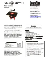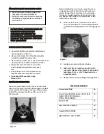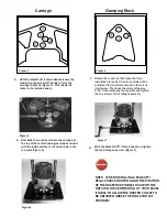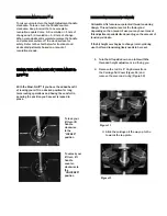
Figure 9
1.
Place the insert ring into the center hole of
the Lift’s top plate (Fig. 5).
2.
With the insert wrench provided, insert the
prongs of the wrench into the
corresponding holes in the insert ring and
turn the insert ring counter clockwise to
tighten.
Turn the insert wrench clockwise to loosen and
remove the ring. If the insert ring becomes too tight
to loosen with hand pressure, a tap clockwise on the
insert wrench with a block of wood will loosen it.
INSTALLING A JESSEM LIFT IN A CUSTOM
ROUTER TABLE APPLICATION
A JessEm router lift is similar to using a router mounting
plate. Your table top must have a port machined into the
top. JessEm offers solid phenolic router tables tops with
pre-machined ports for all JessEm router lifts. If you are
installing this Lift in a custom table application you will
have to fabricate this opening yourself. JessEm offers a
separate template for this operation. See your JessEm
distributor for the proper template for your JessEm
Mast-R-Lift II.
ADJUSTING THE FIT IN THE TABLE PORT
Your Mast-R-Lift™ II comes with adjustable snugger
bars to allow for a tight fit in the table top
opening and eliminate any movement of the
plate. Use the 3/16” hex key provided to loosen
the cap screws on the snugger bars. Move the bars
out slightly and check for fit. Adjust again if
necessary. (Figure 9)
Figure 10
Figure 8
LEVELING THE LIFT IN THE TABLE TOP
1.
With the Mast-R-Lift™ II in the table top
opening,
install (10) set screws into the
holes around the
lift perimeter. Adjust
(Figure 8) the four corners first to align the
lift
surface to the table surface so that
both are flush.
Adjust the remaining set
screws on the sides to
provide added
support.
TAB-LOC PHENOLIC INSERT RINGS
Your Mast-R-Lift™ II comes with one 2” insert ring with
a pre-drilled center hole. Additional ring sets are
available with different diameter pre-drilled holes
and/or no pre-drilled holes for creating your own
custom center hole diameters. See your JessEm
distributor for these and other accessories
The Mast-R-Lift II is manufactured to precise tolerances.
Due to the manufacturing tolerances of the different
router motors that the Mast-R-Lift II will accommodate,
you may find that your Lift is not as smooth as it should
be after the router is installed. To correct this, first: raise
the Lift carriage with the router installed to a position
close to the top plate. Then, loosen the two 5/16- 18
socket screws holding each shaft onto the top plate a
quarter of a turn and re-tighten. This relieves any stress
on the shafts to center themselves with respect to the
carriage after the router is installed ensuring there is no
resistance in the movement of the carriage up and down.


