LOCKING THE TABLE SLIDE POSITION
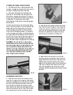
1. The table slide has a spring loaded, shot
pin type, locking knob under the front end of
the lower carriage assembly (Fig. 12).
2. Pull down and twist the knurled knob
until the “T” knob slides into the groove on
the shaft to engage the shot pin. To release
the shot pin, pull and twist the knurled knob
so that the “T” knob sits on the shaft
perpendicular to the groove and disengages
the shot pin.
3. There are four stops for locking the table
slide in a fixed position. You can position the
table slide to be flush with the rear of the
lower carriage assembly, or flush with the
front of the carriage assembly, or centered
on the carriage assembly, or positioned with
the table slide at full extension to the front of
the saw for safely holding the table slide in a
fixed position while placing the workpiece
onto the table slide in preparation for cutting.
WARNING! - Do not sit on, or lean on the
sliding table at any time and especially not
when the table slide is at full extension. Do
not overload the sliding table with heavy
objects or a heavy workpiece at any time as
you may risk causing the table saw to tip
over and cause damage to the machine
and/or injury to the operator.
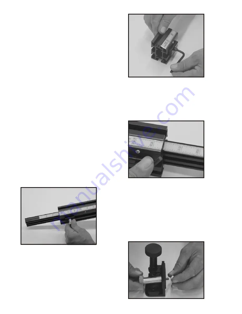
ASSEMBLING THE FENCE
1. Take the miter fence (item #4 from the
parts list on page 2) and observe that inside
the fence extrusion is the extension rod. Hold
the fence level and being careful not to let
the extension rod slide out and fall on the
floor, loosen the extension locking knob and
slide the extension rod out (Fig. 13) to allow
the attaching of the fence extension block.
FIG. 13
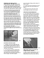
FIG. 14
2. Take the fence extension block (item #3
from the parts list on page 2) and using the
3/16” hex wrench, loosen the 1/4”-20 cap
screw on the extension block to loosen the
internal nut sufficiently to allow insertion
onto the fence extension rod (Fig. 14).
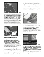
FIG. 15
FIG. 16
3. Slide the fence extension rod into the
extension block ensuring the internal nut is
aligned with the T-slot on the extension rod.
Position the extension block so the inner
edge of the extension block lines up with the
“red” line at the 30 inch mark on the scale
(Fig. 15). Re-tighten the cap screw on the
extension block clamping nut to hold it in this
position.


