background image

 16 

Note:

 If conveyor belt continually tracks to one side 

of the machine, reversing the belt on the conveyor 
table  may  remedy  the  problem.  To  make  sure  the 
conveyor  table  is  not  twisted,  place  a  level  on  the 
conveyor table. Level the machine if needed. If there 
is still a problem, proceed with the steps below: 

Step 1

: Check conveyor drive roller and driven roller 

to make sure they are parallel to surface of conveyor 
table.  To  do  this,  first  center  conveyor  belt  on  the 
conveyor  table.  Then  lay  a  straight-edge  on  the 
exposed edge of conveyor table on left (outboard) 
side,  extending  it  over  the  roller.  Note  distance 
between roller and straightedge. 

Step 2:

 Now repeat Step 1 on right (inboard) side of 

conveyor. Compare the measurements from side to 
side.  If  they  are  not  equal,  loosen  one  of  the 
brackets that hold the roller in place. Tip this bracket 
until distance between roller and straight-edge are 
equal from side to side, then tighten bracket. 

9.4

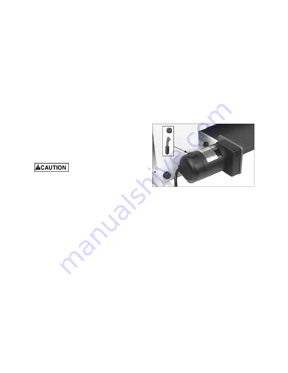
  Commutator brush inspection 

To maintain motor efficiency, inspect the two carbon 
brushes  every  two  months,  or  more  frequently  if 
sander is heavily used. Stalling or loss of power may 
be a symptom of worn carbon brushes. If one brush 
is worn out, replace both at the same time. 


Continued  use  of  damaged  or 

worn  brushes  may  result  in  damage  to  motor 
armature. 

1.  Unplug sander from power source. 

2.  Unscrew  and  remove  cap  with  flat  blade 

screwdriver. See Figure 9-4. 

3.  Gently pry up an edge of the brass clip, until the 

spring causes it to disengage from hole. (Notice 
orientation of brush as you remove it; it should 
be  inserted  in  the  same  manner;  curvature  of 
brush will match curvature of motor.) 

4.  Pull  out  brush  and  inspect.  Brush  should  be 

replaced if any of the following are discovered: 


Brush has worn to about 1/2-inch long. 


Signs of crumbling, burning or breaking. 


End of brush is rough or pitted. 


Abnormal coloration of spring 


Broken lead in spring 


Collapsed spring 

5.  Install new brush (or reinstall current brush) and 

gently  press  it  all  the  way  into  hole  until  the 
brass clip is secured. 

6.  Install cap. 

7.  Repeat for other brush. 

NOTE:    It  is  recommended  that  sander  be  run 
without  load  for  several  minutes  to  seat  new 
brushes. 


Figure 9-4 

9.5

  Additional servicing 

Any additional servicing should be performed by an 
authorized service technician.


Summary of Contents for 169616

Page 1: ...and Parts Manual Bench top Drum Sander Model JWDS 1020 JET 427 New Sanford Road LaVergne Tennessee 37086 Part No M 723510 Ph 800 274 6848 Edition 1 06 2019 www jettools com Copyright 2019 JET This pdf...

Page 2: ...ower source 14 Remove adjusting keys and wrenches Form a habit of checking to see that keys and adjusting wrenches are removed from the machine before turning it on 15 Keep safety guards in place at a...

Page 3: ...rous environment Don t use power tools in damp or wet location or expose them to rain Keep work area well lighted Familiarize yourself with the following safety notices used in this manual This means...

Page 4: ...ng methods choice of stock selection of abrasives etc Additional knowledge may be obtained from experienced users or trade articles Whatever accepted methods are used always make personal safety a pri...

Page 5: ...ns 12 8 1 Basic Operating Procedure 12 8 2 Switch safety key 13 8 3 Circuit breaker reset 13 8 4 Setting depth of cut 13 8 5 Establishing drum height 13 8 6 Maximum performance tips 14 9 0 User mainte...

Page 6: ...5 A Sound emission 2 70 6 dB at 100cm 3 3ft 74 7 dB at 50cm 1 6ft Capacities Maximum board width single pass 10 in 254 mm Maximum board width two passes 20 in 508 mm Maximum board thickness 3 in 76 2...

Page 7: ...fe operating levels As workplace conditions vary this information is intended to allow the user to make a better estimation of the hazards and risks involved only 3 Use of a carrier or backer board no...

Page 8: ...brasive life The JWDS 1020 is equipped with a 4 inch dust collection port Secure a 4 inch dust collection hose not provided to the port with a hose clamp see Figure 5 2 Connect to a high volume dust c...

Page 9: ...nder comes with a plug designed for use on a circuit with a grounded outlet that looks like the one pictured in Figure 6 1 Before connecting to power source be sure switch is in off position It is rec...

Page 10: ...e a drop in line voltage resulting in loss of power and overheating Table 2 shows correct size to use depending on cord length and nameplate ampere rating If in doubt use the next heavier gauge The sm...

Page 11: ...has been achieved sect 7 3 1 2 Turn on conveyor and set to maximum speed Watch for tendency of conveyor belt to drift to one side of conveyor 3 If conveyor drifts slightly loosen two screws A Figure 7...

Page 12: ...osition 7 5 Tension roller adjustment The infeed and outfeed rollers are tensioned to provide downward pressure on the workpiece to prevent slippage on the feed conveyor Tension rollers have been set...

Page 13: ...can still be rotated by hand while just contacting stock Do not start drum while in contact with stock 3 Without changing drum height turn on conveyor and run the stock out from under the drum Start...

Page 14: ...en ripped at the proper angle to the face before the sanding process When edge sanding stock that is less than 3 4 wide or more than 2 high it is good procedure to stack and clamp several pieces toget...

Page 15: ...offset the center of balance Check all set screws for tightness on parts such as bearings conveyor table and couplings Figure 9 1 9 2 Drum maintenance The drum should not require removal from the mac...

Page 16: ...two months or more frequently if sander is heavily used Stalling or loss of power may be a symptom of worn carbon brushes If one brush is worn out replace both at the same time Continued use of damage...

Page 17: ...ccept stains evenly This will vary by type of wood Oak for example is susceptible to burnishing because of its open pores 10 2 Cleaning abrasive strips Regularly clean the abrasive strip on the drum w...

Page 18: ...erminals or worn insulation Low voltage Correct low voltage conditions Incorrect fuse or circuit breaker in power line Install correct fuse or circuit breaker Loud repetitive noise or vibration coming...

Page 19: ...conveyor belt Replace conveyor belt Ripples in sanded surface A Non uniformly spaced ripples B Uniformly spaced ripples A Uneven feed rate Conveyor belt slipping see above Board slips on conveyor belt...

Page 20: ...60 9060 Premium Ready To CutTM Abrasive Strip 60 Grit 60 9080 Premium Ready To CutTM Abrasive Strip 80 Grit 60 9100 Premium Ready To CutTM Abrasive Strip 100 Grit 60 9120 Premium Ready To CutTM Abras...

Page 21: ...21 13 1 1 JWDS 1020 Drum Sander Exploded View...

Page 22: ...1 6T 8 27 TS 2249352 Socket Head Button Screw M10 x 1 5P x 35L 2 28 TS 1502011 Socket Head Cap Screw M5 x 0 8P x 8L 1 29 JWDS1020 129 Pointer 1 30 6290832 Phillips Pan Hd Machine Screw M5 x 0 8P x 8L...

Page 23: ...82 TS 2246162 Socket Head Button Screw M6 x 1 0P x 16L 6 83 TS 1521021 Socket Head Set Screw M4 x 0 7P x 5L 2 84 JWDS1632 204 Belt Motor Plate 1 85 F010985 Socket Head Flat Screw M6 x 1 0P x 35L 2 86...

Page 24: ...24 14 0 Electrical Connections for JWDS 1020 GM GM Sanding Motor Belt Motor L1 L2 Circuit Board Overload Relay Switch Motor Shroud...

Page 25: ...ce Centers located throughout the United States For the name of an Authorized Service Center in your area call 1 800 274 6846 or use the Service Center Locator on the JET website More Information JET...

Page 26: ...26 This page intentionally left blank...

Page 27: ...27 This page intentionally left blank...

Page 28: ...28 427 New Sanford Road LaVergne Tennessee 37086 Phone 800 274 6848 www jettools com...

Reviews: