background image

 18 

10.6

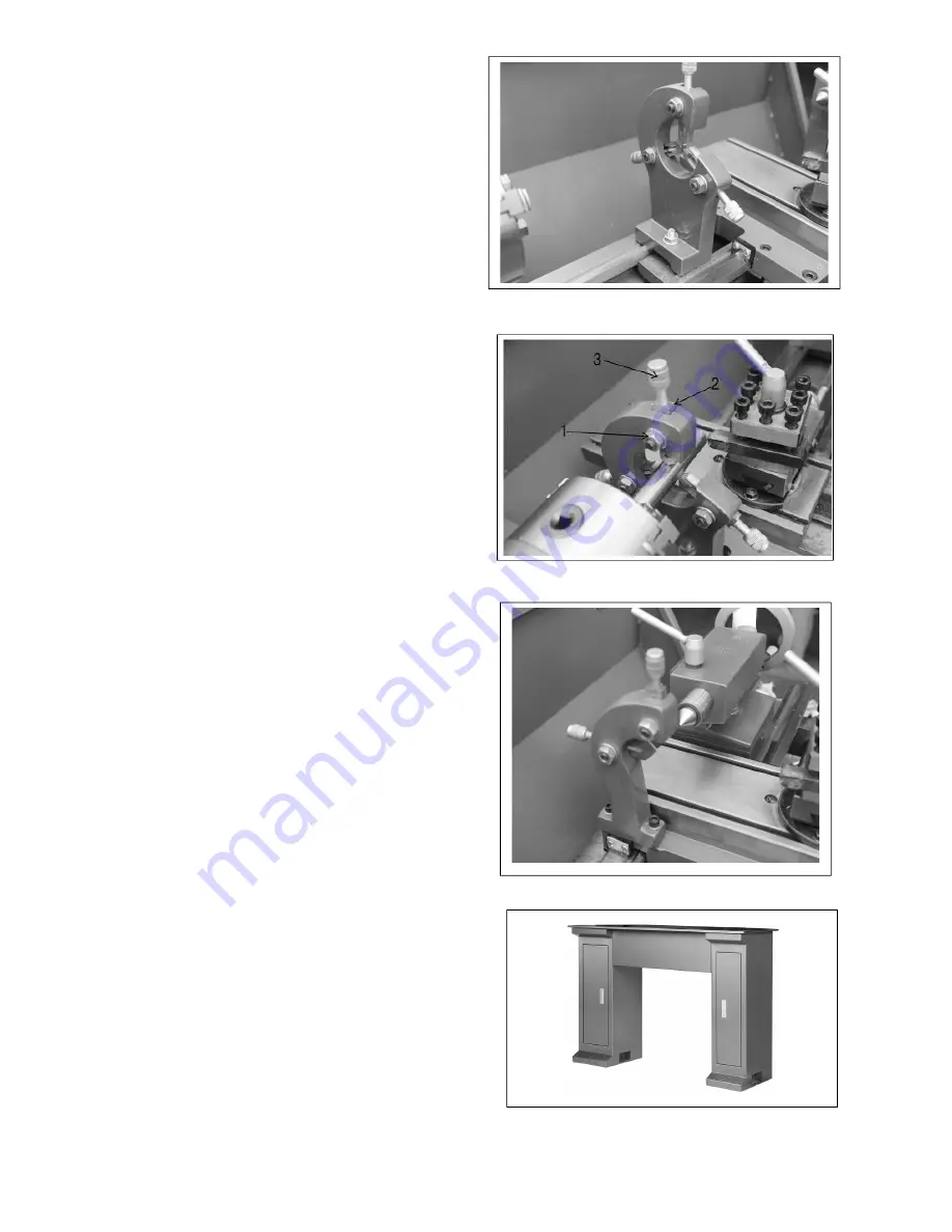
  Steady rest 

The steady rest (Figure 25) serves as a support for 
shafts on the free tailstock end. For many 
operations, the tailstock cannot be used as it 
obstructs the turning tool or drilling tool, and 
therefore, must be removed from the machine. 

The steady rest, which functions as an end support, 
ensures chatter-free operation. The steady rest is 
mounted on the bedways and is secured from below 
with a locking plate. The sliding fingers require 
continuous lubrication at the contact points to 
prevent premature wear. 


10.7

  Setting the steady rest 

1.  Loosen three hex nuts (1, Figure 26). 

2. 

Loosen knurled screw (3, Figure 26) and open 
the sliding fingers (2, Figure 26) until the steady 
rest can be moved with its fingers around the 
workpiece. Secure the steady rest in position.


3. 

Tighten knurled screws so that fingers are snug 
but not tight against the workpiece. Tighten 
three nuts (1, Figure 26). Lubricate the sliding 
points with machine oil.


4. 

When, after prolonged operation, the jaws 
show wear, the tips of the fingers may be filed 
or re-milled.


10.8

  Follow rest  

The follow rest (Figure 27) is mounted on the saddle 
and follows the movement of the turning tool. Only 
two sliding fingers are required. The place of the 
third finger is taken by the turning tool. The follow 
rest is used for turning operations on long, slender 
workpieces. It prevents flexing of the workpiece 
under pressure from the turning tool. 

Set the fingers snug to the workpiece but not overly 
tight. Lubricate the fingers during operation to 
prevent premature wear. 


10.9

  Stand (optional) 

A steel stand specially designed for this lathe is 
available from JET (Figure 28). Contact your 
distributor or JET to order. 

Stand # 321375 for BDB-919 Lathe. 

Stand # 321377 for BDB-929 Lathe. 


Figure 25


Figure 26 


Figure 27 


Figure 28 


Summary of Contents for 321378

Page 1: ...Belt Drive Bench Lathes Models BDB 919 929 JET 427 New Sanford Road LaVergne Tennessee 37086 Part No M 321378 Ph 800 274 6848 Edition 2 12 2020 www jettools com Copyright 2017 JET For machines with s...

Page 2: ...having a nominal rating less than 150 volts This tool is intended for use on a circuit that has an outlet that looks like the one illustrated in Sketch A The tool has a grounding plug that looks like...

Page 3: ...CE TOOL It will do the job better and safer at the rate for which it was designed 12 USE RIGHT TOOL Don t force tool or attachment to do a job for which it was not designed 13 WEAR PROPER APPAREL Do n...

Page 4: ...mber the heavier the cord Ampere Rating Volts Total length of cord in feet 120 V 25 ft 50 ft 100 ft 150 ft 240 V 50 ft 100 ft 200 ft 300 ft More than Not more than AWG 0 6 18 16 16 14 6 10 18 16 14 12...

Page 5: ...3 Drill chuck optional 17 10 4 Morse taper arbor optional 17 10 5 Live center optional 17 10 6 Steady rest 18 10 7 Setting the steady rest 18 10 8 Follow rest 18 10 9 Stand optional 18 10 10 Four way...

Page 6: ...ist 44 13 14 1 Follow Rest Exploded View 45 13 14 2 Follow Rest Parts List 45 13 15 1 BD 919 Bed Assembly Exploded View 46 13 15 2 BDB 919 Bed Assembly Parts List 47 13 16 1 BDB 929 Bed Assembly Explo...

Page 7: ...e contact your local supplier or JET JET can also be reached at our web site www jettools com Retain this manual for future reference If the machine transfers ownership the manual should accompany it...

Page 8: ...sh guard Steel Dimensions Bed width 4 1 2 in Overall dimensions LxWxH 41 x 22 x 20 in 51 x 22 x 20 in Shipping dimensions LxWxH 41 x 22 x 22 in 51 x 22 x 22 in Weights Net weight approx 250 lbs 287 lb...

Page 9: ...re mounted 1 52T Gear J 1 48T Gear K 1 46T Gear L 1 45T Gear M 1 44T Gear N 1 40T Gear O 1 38T Gear P 2 32T Gear Q 1 30T Gear R 1 28T Gear pre mounted 1 Tension Roller Lever S 1 Handle T 1 Female Chuc...

Page 10: ...that the BDB 919 and BDB 929 Lathes be connected to a dedicated minimum 25 amp circuit with a circuit breaker or time delay fuse Local codes take precedence over recommendations 7 0 General descriptio...

Page 11: ...lide and the cross slide travel in dovetailed slides and have gibs adjustable nuts and graduated collars A four way tool post is fitted on the top slide Figure 6 The four way tool post can be converte...

Page 12: ...bearing on both ends The nut and setscrew on the right end are designed to take up play on the leadscrew 7 7 Gear box The gearbox Figure 11 is made from high quality cast iron and is mounted on the le...

Page 13: ...oss Slide Handwheel 6 Top Slide Handwheel 7 Longitudinal Lock Screw 8 Tool Post 9 Tailstock Spindle Handwheel 10 Tailstock Spindle Clamping Lever 11 Tailstock Locking Lever 12 Tailstock Off Set Adjust...

Page 14: ...e obtained by using shims under the tool Figure 13 When turning the tool has a tendency to bend under pressure For best results tool overhang should be kept to a minimum of 3 8 or less 9 2 Manual turn...

Page 15: ...constant adjustment until the piece is absolutely true checks the zero position of the tailstock 9 5 Taper turning by setting the top slide By angling the top slide tapers may be turned Figure 17 Loos...

Page 16: ...ut When the tool reaches the part it will cut the initial threading pass When the tool reaches the end of the cut stop the machine by turning the motor off and at the same time back the tool out of th...

Page 17: ...ent lathe chuck This special chuck Figure 22 has four independently adjustable chuck jaws These permit the holding of asymmetrical pieces and enable the accurate set up of cylindrical pieces 10 3 Dril...

Page 18: ...nurled screws so that fingers are snug but not tight against the workpiece Tighten three nuts 1 Figure 26 Lubricate the sliding points with machine oil 4 When after prolonged operation the jaws show w...

Page 19: ...1 Adjustment of main spindle bearings The main spindle bearings are adjusted at the factory If end play becomes evident after considerable use the bearings may be adjusted Loosen setscrew 1 Figure 31...

Page 20: ...Remove the compound slide and adjust screw 1 Figure 34 until the backlash between the spindle and the nut is eliminated For operator convenience the compound may be located in two positions on the cr...

Page 21: ...both nuts 11 7 Replacing the V belt Remove tension on the V belt by pulling lever toward front of the machine Figure 37 Remove belt from the pulley and replace with new belt Move lever toward motor t...

Page 22: ...s of oil into oil ball on leadscrew bracket 7 Lightly coat screw and guides of top slide with oil 8 1 to 2 squirts of oil into oil ball on top of tailstock body 9 Lightly coat guides of carriage with...

Page 23: ...m to 5 00 p m CST Having the Model Number and Serial Number of your machine available when you call will allow us to serve you quickly and accurately Non proprietary parts such as fasteners can be fo...

Page 24: ...19 012 Gear 40T 1 13 BDB919 013 Pulley 1 14 BDB919 014 Nut M28X1 1 15 BDB919 015 Bushing 1 16 TS 1524011 Socket Set Screw M8 1 25X8 1 17 BDB919 017 Shaft 1 18 BDB919 018 Bushing 2 19 BDB919 019 Gear 8...

Page 25: ...25 13 2 1 Drive Belt Assembly Exploded View...

Page 26: ...y 1 113 BDB919 113 Pulley 1 114 F006041 C Retaining Ring Ext 12MM 1 115 BDB919 021 Ball Oiler 6MM 1 116 BDB919 116 Spacer 1 117 BDB919 117 Collar 1 118 BDB919 118 Pulley 1 119 BDB919 119 Large Flat Wa...

Page 27: ...ng Ring Int 28mm 1 206 BDB919 206 Washer 1 207 BDB919 207 Spring 1 208 BDB919 208 Stud Bolt 1 209 TS 1524011 Socket Set Screw M8 1 25X8 1 210 TS 1503031 Hex Socket Hd Cap Screw M6 1 0X12 1 211 BDB919...

Page 28: ...r 20mm 1 309 BDB919 021 Ball Oiler 6mm 1 310 BDB919 310 Washer 1 311 F012070 Roll Pin 4x12mm 1 312 BDB919 312 Gear 56T 1 313 BDB919 313 Spacing Ring 1 314 TS 1503011 Hex Socket Hd Cap Screw M6 1 0X8 1...

Page 29: ...29 13 5 1 Electrical Exploded View...

Page 30: ...H BE102C 1 409 BDB919 409 Rubber Gasket 2X15mm 1 410 TS 1502011 Hex Socket Hd Cap Screw M5 0 8x8 9 411 TS 1550031 Flat Washer 5mm 9 412 BDB919 412 Electrical Box Cover 1 413 F009875 Socket Hd Button S...

Page 31: ...506 BDB919 506 Acrylic Sheet 1 507 TS 1502021 Hex Socket Hd Cap Screw M5 0 8x10 2 508 TS 1550031 Flat Washer 5mm 2 509 BDB919 509 Tube 1 510 BDB919 510 Shaft 1 511 TS 1522011 Socket Set Screw M5 0 8X...

Page 32: ...32 13 7 1 Gear Box Exploded View...

Page 33: ...6 BDB919 626 Shift Lever 1 627 BDB919 627 Fork 1 628 F006043 C Retaining Ring Ext 15mm 5 629 BDB919 629 Gear 20T 1 25 1 630 BDB919 630 Bracket 1 631 TS 1502031 Hex Socket Hd Cap Screw M5 0 8X12 8 632...

Page 34: ...34 Index No Part No Description Size Qty 705 BDB919 705 Gear 12T 1 25M 1 706 BDB919 706 Screw 1 707 TS 1502021 Hex Socket Hd Cap Screw M5 0 8X10 1 708 BDB919 708 Washer 1 709 BDB919 709 Handle 1...

Page 35: ...35 13 8 1 Apron I Exploded View...

Page 36: ...1 723 KEY3308 Key Double Rd Hd A3X3X8 2 724 AHJ12 25 C Retaining Ring Ext 14mm 1 725 BDB919 725 Shaft 1 726 JWDP12 078 Key Double Rd Hd A4X4X6 1 727 BDB919 727 Gear 41T 1M 1 728 BDB919 728 Handle 1 7...

Page 37: ...759 BDB919 759 Thread Dial 1 760 BDB919 760 Thread Dial Body 1 761 TS 1550041 Flat Washer 6mm 1 762 TS 1503131 Hex Socket Hd Cap Screw M6 1 0X60 1 763 BDB919 763 Worm Gear 64T 0 5Mn 1 764 TS 2361081 L...

Page 38: ...38 13 10 2 Saddle and Cross Slide Exploded View...

Page 39: ...0X10 1 820 TS 1523031 Socket Set Screw M6 1 0X10 1 821 F004021 Dowel Pin 3X24mm 4 822 TS 1521041 Socket Set Screw M4 0 7X10 3 823 BDB919 823 Hex Nut M4 3 824 BDB919 824 Slide Block 1 825 TS 1550041 F...

Page 40: ...40 13 11 1 Compound Slide Exploded View...

Page 41: ...503021 Hex Socket Hd Cap Screw M6 1 0X10 3 915 TS 1521071 Socket Set Screw M4 0 7X20 3 916 TS 1540021 Hex Nut M4 3 917 TS 1540041 Hex Nut M6 2 918 5783461 Roll Pin 3X8mm 1 919 130603018 Roll Pin 3X14m...

Page 42: ...42 13 12 1 Tailstock Exploded View...

Page 43: ...le 1 1014 BDB919 711 Leaf Spring 1 1015 BDB919 1015 Lever 1 1016 BDB919 1016 Handwheel 1 1017 BDB919 1017 Nut 1 1018 BDB919 1018 Set Screw M8X8 1 1019 BDB919 1019 Handle 1 1020 BDB919 1020 Handle Scre...

Page 44: ...on Size Qty 1101 BDB919 1101 Rest Casting 1 1102 BDB919 1102 Jaw 3 1103 BDB919 1103 Screw 3 1104 TS 2361081 Lock Washer 8mm 3 1105 TS 1541031 Hex Nut M8 4 1106 BDB919 1106 Adjusting Screw 3 1107 BDB91...

Page 45: ...escription Size Qty 1201 BDB919 1201 Follow Rest Casting 1 1202 BDB919 1202 Jaw 2 1203 BDB919 1203 Screw 2 1204 BDB919 1204 Adjusting Screw 2 1205 TS 1541031 Hex Nut M8 2 1206 TS 2361081 Lock Washer 8...

Page 46: ...46 13 15 1 BD 919 Bed Assembly Exploded View...

Page 47: ...1310 BDB919 1310 Motor 3 4HP 550w 1PH 1 1311 BDB919 1311 Washer 2 1312 PM1000 188 Socket Set Screw M6X35 4 1313 TS 2361061 Lock Washer 6mm 4 1314 TS 1540041 Hex Nut M6 4 1315 BDB919 1315 Large Washer...

Page 48: ...48 13 16 1 BDB 929 Bed Assembly Exploded View...

Page 49: ...1310 BDB919 1310 Motor 3 4HP 550w 1PH 1 1311 BDB919 1311 Washer 2 1312 PM1000 188 Socket Set Screw M6X35 4 1313 TS 2361061 Lock Washer 6mm 4 1314 TS 1540041 Hex Nut M6 4 1315 BDB919 1315 Large Washer...

Page 50: ...e Plate 190mm 1 1404 BDB919 1404 Spindle Bar 1 1405 BDB919 1405 Chuck Bar 1 1406 BDB919 1406 Dead Center MT2 MT2 2 1407 BDB919 1407 Oil Bottle 1 1408 JHL610 901 Hex Wrench 2mm 2mm 1 1409 TS 152704 Hex...

Page 51: ...ru 1510 1 1501 BDB919 1501 Left Stand H 760mm 1 1502 BDB919 1502 Door Latch Assembly 2 1503 BDB919 1503 Stand Plate L 385mm 2 1504 BDB919 1504 Right Stand H 760mm 1 1505 TS 1540071 Hex Nut M10 4 1506...

Page 52: ...1510 1 1501 BDB919 1501 Left Stand H 760mm 1 1502 BDB919 1502 Door Latch Assembly 2 1503 1 BDB929 1503 1 Stand Plate L 645mm 2 1504 BDB919 1504 Right Stand H 760mm 1 1505 TS 1540071 Hex Nut M10 4 150...

Page 53: ...14 0 Wiring diagram for BDB 919 929 Lathes 1 1 1 2 X V 2 W 1 C 1 C 2 M 1 U 2 W 2 V 1 U 1 3 1 1 0 7 5 4 2 9 8 6 S A P E N L X X X X X X X X X 9 1 0 7 8 5 6 3 4 1 2 R O L KM KM KM S B 1 S B 2 15 16 KM...

Page 54: ...54 15 0 Speed and threading charts...

Page 55: ...tional action needed JET has Authorized Service Centers located throughout the United States For the name of an Authorized Service Center in your area call 1 800 274 6846 or use the Service Center Loc...

Page 56: ...56 427 New Sanford Road LaVergne Tennessee 37086 Phone 800 274 6848 www jettools com...

Reviews: