background image

8

5.0

Electrical connections

All electrical connections must

be done by a qualified electrician in compliance
with all relevant codes and ordinances. Failure
to comply may result in serious injury.

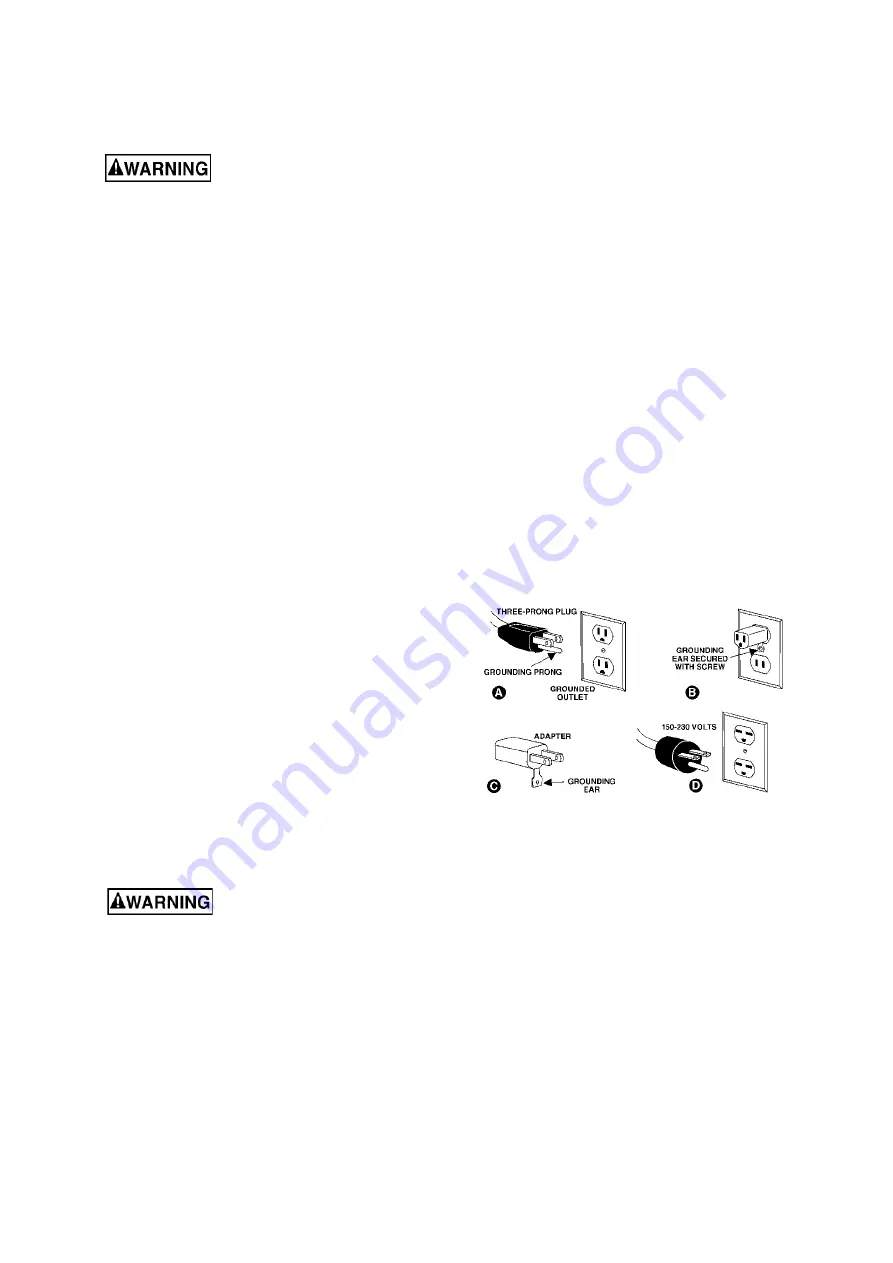
The IAFS-1700 and IAFS-2400 units are rated at
115-volt only, and are provided with a 5-15P plug
designed for use on a circuit with a

grounded outlet

that looks like the one pictured in

A

, Figure 5-1.

The IAFS-3000 is rated at 230 volt only, and is
provided with a 6-15P plug designed for use on a
circuit with a

grounded outlet

that looks like the one

pictured in

D

, Figure 5-1.

Before connecting to power source, be sure switch
is in

off

position.

It is recommended that the IAFS unit be connected
to a dedicated minimum 15 amp circuit with circuit
breaker or time-delay fuse marked “D”.

Local

codes take precedence over recommendations.

5.1

GROUNDING INSTRUCTIONS

1. All Grounded, Cord-connected Tools:

In the event of a malfunction or breakdown,
grounding provides a path of least resistance for
electric current to reduce the risk of electric shock.
This tool is equipped with an electric cord having an
equipment-grounding conductor and a grounding
plug. The plug must be plugged into a matching
outlet that is properly installed and grounded in
accordance with all local codes and ordinances.

Do not modify the plug provided - if it will not fit the
outlet, have the proper outlet installed by a qualified
electrician.

Improper connection of the equipment-grounding
conductor can result in a risk of electric shock. The
conductor with insulation having an outer surface
that is green with or without yellow stripes is the
equipment-grounding

conductor.

If

repair

or

replacement of the electric cord or plug is necessary,
do not connect the equipment-grounding conductor
to a live terminal.

Check

with

a

qualified

electrician or service pe

r

sonnel if the grounding

instructions are not completely understood, or if
in doubt as to whether the tool is properly
grounded. Failure to comply may cause serious
or fatal injury.

Use only 3-wire extension cords that have 3-prong
grounding plugs and 3-pole receptacles that accept
the tool's plug.

Repair

or

replace

damaged

or

worn

cord

immediately.

2. Grounded, cord-connected tools intended for use
on a supply circuit having a nominal rating less than
150 
volts:

This tool is intended for use on a circuit that has an
outlet that looks like the one illustrated in

A,

Figure

5-1. An adapter, shown in

B

and

C

, may be used to

connect this plug to a 2-pole receptacle as shown in

B

if a properly grounded outlet is not available. The

temporary adapter should be used only until a
properly grounded outlet can be installed by a
qualified electrician.

This adapter is not permitted in

Canada.

The green-colored rigid ear, lug, and the

like, extending from the adapter must be connected
to a permanent ground such as a properly grounded
outlet box.

3. Grounded, cord-connected tools intended for use
on a supply circuit having a nominal rating between
150 - 250 volts, inclusive:

This tool is intended for use on a circuit that has an
outlet that looks like the one illustrated in

D,

Figure

5-1. The tool has a grounding plug that looks like the
plug illustrated in

D

. Make sure the tool is connected

to an outlet having the same configuration as the
plug. No adapter is available or should be used with
this tool. If the tool must be reconnected for use on
a different type of electric circuit, the reconnection
should be made by qualified service personnel; and
after reconnection, the tool should comply with all
local codes and ordinances.

Figure 5-1

5.2

Extension cords

The use of extension cords is discouraged; try to
position equipment within reach of the power
receptacle. If an extension cord becomes necessary,
be sure it is heavy enough to carry the current your
product will draw. An undersized cord will cause a
drop in line voltage resulting in loss of power and
overheating.

Table 1 shows recommended size to use depending
on cord length and nameplate ampere rating. If in
doubt, use the next heavier gauge. The smaller the
gauge number, the heavier the cord.

Summary of Contents for 415100

Page 1: ...ad LaVergne Tennessee 37086 Part No M 415100 Ph 800 274 6848 Edition 1 11 2020 www jettools com Copyright 2020 JET Operating Instructions and Parts Manual Industrial Air Filtration System Models IAFS 1700 IAFS 2400 IAFS 3000 ...

Page 2: ...eiling mounted bottom of filtration unit must be at least 7 feet from the floor 13 If ceiling mounted mounts must be anchored to building structure which will support the weight of the air filtration unit Never mount to surfaces such as dry wall or false ceiling grids 14 To reduce risk of electric shock do not expose filtration unit to water or rain 15 Never duct a machine directly into the air fi...

Page 3: ...ecautions general operating procedures maintenance instructions and parts breakdown Your machine has been designed and constructed to provide consistent long term operation if used in accordance with the instructions as set forth in this document If there are questions or comments please contact your local supplier or JET JET can also be reached at our web site www jettools com Retain this manual ...

Page 4: ...lacement 11 10 2 Additional servicing 11 11 0 Optional accessories 11 12 0 Replacement parts 11 12 1 1 IAFS 1700 Industrial Air Filtration System Exploded View 12 12 1 2 IAFS 1700 Industrial Air Filtration System Parts List 13 12 2 1 IAFS 2400 Industrial Air Filtration System Exploded View 14 12 2 2 IAFS 2400 Industrial Air Filtration System Parts List 15 12 3 1 IAFS 3000 Industrial Air Filtration...

Page 5: ...372 1129 798 1946 1640 1269 2780 2364 1711 Total pressure Pa 3 53 2 46 1 18 7 16 5 10 3 04 7 65 5 60 2 94 Total pressure efficiency t 0 32 0 24 0 12 0 85 0 65 0 41 0 64 0 52 0 28 Filters installed Air flow CFM 1107 1008 805 1415 1325 1182 2099 1953 1666 Total pressure Pa 2 35 1 96 1 18 3 73 3 34 2 65 4 32 3 83 2 75 Total pressure efficiency t 0 19 0 20 0 13 0 41 0 43 0 37 0 34 0 36 0 28 Blower spe...

Page 6: ...r a Class B digital device pursuant to Part 15 of the FCC Rules These limits are designed to provide reasonable protection against harmful interference in a residential installation This equipment generates uses and can radiate radio frequency energy and if not installed and used in accordance with the instructions may cause harmful interference to radio communications However there is no guarante...

Page 7: ...7 4 1 Mounting hole spacing All measurements in millimeters Figure 4 1 Figure 4 2 ...

Page 8: ...s properly grounded Failure to comply may cause serious or fatal injury Use only 3 wire extension cords that have 3 prong grounding plugs and 3 pole receptacles that accept the tool s plug Repair or replace damaged or worn cord immediately 2 Grounded cord connected tools intended for use on a supply circuit having a nominal rating less than 150 volts This tool is intended for use on a circuit that...

Page 9: ...ight of the unit Do not mount to dry wall or false ceiling grids Failure to comply may cause serious injury and property damage If setting unit on a table or bench remove the adhesive from the 4 foot pads and press the pads to the bottom of the unit near the corners Remove back cover of remote controller and install 9 volt battery Reinstall cover The holder for the remote controller can be mounted...

Page 10: ...10 Figure 9 1 Figure 9 2 Figure 9 3 ...

Page 11: ...rn ON the Air Filtration Unit at the switch 2 On the remote control transmitter press and hold the On Off button for 3 seconds until a beep is heard 3 The remote controller will now operate the Air Filtration Unit 10 2 Additional servicing Any additional servicing should be performed by authorized service personnel 11 0 Optional accessories Charcoal carbon filters are especially effective at trapp...

Page 12: ...12 12 1 1 IAFS 1700 Industrial Air Filtration System Exploded View ...

Page 13: ...07 Inner Filter 1 20 415105 Charcoal Filter Optional 1 21 IAFS1700 021 Cabinet Assembly 1 22 IAFS1700 022 Eye Bolt M6 4 23 IAFS1700 023 Fixing Plate 2 24 IAFS1700 024 Gasket 2 25 330025 Air Diffuser 1 26 IAFS RC Remote Control Transmitter includes holder 1 9 volt Battery local purchase 1 27 IAFS1700 027 Foam foot pad 4 28 IAFS1700 028 Blower Assembly includes 101 thru 111 1 101 330005 Motor Gasket...

Page 14: ...14 12 2 1 IAFS 2400 Industrial Air Filtration System Exploded View ...

Page 15: ... Cabinet Assembly 1 22 330025 Air Diffuser 1 23 JWBS14DP 6 8 Carriage Bolt M8 x 16 4 24 TS 1540061 Hex Nut M8 10 25 IAFS RC Remote Control Transmitter includes holder 1 26 IAFS1700 027 Foam foot pad 4 27 IAFS2400 028 Blower Assembly includes 101 thru 114 1 101 TS 1534032 Pan HD Phillips Mach Screw M6 x 10 4 102 TS 1534042 Pan HD Phillips Mach Screw M6 x 12 4 103 IAFS2400 103 Blower Housing 1 104 T...

Page 16: ...16 12 3 1 IAFS 3000 Industrial Air Filtration System Exploded View ...

Page 17: ...r Diffuser 1 22 TS 1540061 Hex Nut M8 10 23 JWBS14DP 6 8 Carriage Bolt M8 x 16 4 24 TS 1490021 Hex Cap Screw M8 x 16 6 25 IAFS RC Remote Control Transmitter includes holder 1 26 IAFS1700 027 Foam foot pad 4 27 IAFS3000 028 Blower Assembly includes 101 thru 114 1 101 TS 1534032 Pan HD Phillips Mach Screw M6 x 10 4 102 TS 1534042 Pan HD Phillips Mach Screw M6 x 12 4 103 IAFS3000 103 Blower Housing 1...

Page 18: ...18 13 0 Electrical Connections 13 1 Wiring diagram for IAFS 1700 ...

Page 19: ...19 13 2 Wiring diagram for IAFS 2400 and IAFS 3000 ...

Page 20: ...itional action needed JET has Authorized Service Centers located throughout the United States For the name of an Authorized Service Center in your area call 1 800 274 6846 or use the Service Center Locator on the JET website More Information JET is constantly adding new products For complete up to date product information check with your local distributor or visit the JET website How State Law App...

Reviews: