background image

JAT-464,-465,-467 Pneumatic Angle Grinder


Setup and Assembly 

Any missing parts or damage should be reported 
immediately to your JET

®

 distributor. Do not use a 

damaged  tool.  Read  this  instruction  manual 
thoroughly for operation, maintenance and safety 
instructions. 

Box contents: 

Angle grinder 

Side handle 

Hex wrench 6mm 

Operation and parts manual  

Product registration card 


Operation 


The  angle  grinder  must  be 

properly  lubricated  before  operation.  See 
“Lubrication” section. 


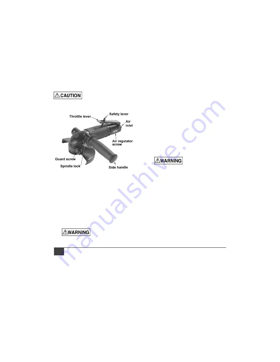
Figure 1 

1. 

Install  side  handle  (Figure  1)  into  threaded 
hole on grinder. 

2. 

Press  spindle  lock  and  rotate  spindle  until 
lock  engages.  Continue  pressing  spindle 
lock while loosening screw counterclockwise 
from  spindle  with  provided  hex  wrench. 
Remove screw and outer flange. 

3. 

Install grinding wheel. Reinstall outer flange 
and screw, and tighten screw while pressing 
spindle lock.  


Make sure spindle screw 

is tight before operating grinder.


4. 

Remove protective cap from air inlet (Figure 
2). If an in-line oiler is not being used, add 4 
or 5 drops of air tool oil (not included) into the 
air inlet. 

5. 

Blow  out  air  line  to  remove  any  dirt  or 
moisture,  then  connect  air  supply  hose  to 
tool. Set air pressure to 90 psi. 

IMPORTANT:

  Connecting  a  quick-change 

coupling  directly  to  the  tool  is  not 
recommended,  as  vibration  may  cause  the 
connection to fail. Instead, add a leader hose 
and  install  any  quick-change  couplings 
farther down the line. 

6. 

Hold grinder with a light but secure grip. Slide 
safety  lever  out  of  the  way  while  pressing 
throttle lever. Pressure against throttle lever 
determines speed of rotation. 

7. 

The  regulator  screw  beneath  the  housing 
can  be  turned  to  adjust  air  intake,  if 
necessary. 

8. 

Position  grinding  wheel  against  workpiece 
with  a  steady  pressure.  Wheel  rotation  is 
clockwise when viewed from above the tool. 
(A  directional  arrow  is  inscribed  at  front  of 
grinder.) 

9. 

Release throttle lever to stop grinder. 

10.  To reposition disc guard, loosen guard screw 

(Figure  1)  and  rotate  guard  to  desired 
position, then retighten screw. 


Do  not  remove  guard 

from  grinder.  Make  sure  guard  screw  is 
tight before operating.


Maintenance 

Lubrication 

The grinder should be lubricated 

daily

 (or before 

each  use)  with  air  tool  oil  through  the  air  inlet. 
During  continual  operation,  it  should  be  re-oiled 
every 1 to 2 hours. This can be done with an in-
line oiler, or manually. If done manually, proceed 
as follows: 

1. 

Disconnect air hose from tool. 

2. 

Place 4 or 5 drops of air tool oil into air inlet. 


Summary of Contents for 505464

Page 1: ...tic Angle Grinder 505464 JAT 464 505465 JAT 465 505467 JAT 467 Operation Parts Manual M 505464 Edition 1 05 2019 JET 427 New Sanford Road LaVergne TN 37086 Ph 800 274 6848 www jettools com Copyright 2019 JET ...

Page 2: ...ecuring the tooling in the retainer and placing the tip against the work surface 11 Do not operate air tool without its guards in place Do not modify the tool 12 Do not operate this tool while tired or under the influence of drugs alcohol or any medication 13 Adopt a comfortable posture with proper balance and maintain secure footing at all times Non slip footwear or anti skid floor strips are rec...

Page 3: ...tive wheel If using a wire brush inspect for loose wires 36 Do not get oil or water on the grinding wheel 37 When operating grinder place grinding wheel against work surface immediately after starting 38 Use proper size grinding wheel that matches the tool s specifications Do not use unapproved flanges bushings to adapt a grinding wheel to the arbor 39 The grinding wheel RPM rating must be the sam...

Page 4: ...this manual may not encompass all possible workplace environments The operator is expected to take appropriate precautions and exercise common sense As with any tool operation safety of operator and bystanders should be first priority If there are questions or comments please contact your local supplier or JET JET can also be reached at our web site www jettools com Record the serial number and pu...

Page 5: ... 6 1 m s2 5 78 m s2 5 43 m s2 Sound power 1 98 0 dB A 98 0 dB A 99 4 dB A Sound pressure 1 87 dB A 87 dB A 88 4 dB A Speed settings Variable throttle lever Variable throttle lever Variable throttle lever Overall length 8 8 in 223 5mm 8 8 in 223 5mm 11 in 279 4mm Housing material Aluminum with composite sleeve Aluminum with composite sleeve Aluminum with composite sleeve Net weight 2 98 lb 1 35 kg ...

Page 6: ...connect air supply hose to tool Set air pressure to 90 psi IMPORTANT Connecting a quick change coupling directly to the tool is not recommended as vibration may cause the connection to fail Instead add a leader hose and install any quick change couplings farther down the line 6 Hold grinder with a light but secure grip Slide safety lever out of the way while pressing throttle lever Pressure agains...

Page 7: ...regular basis 6 Air line pressure may be increased accordingly to compensate for extra long air hoses usually over 25 feet Inside diameter of hose should be minimum 3 8 inch General Air Tool Information If the air tool is not performing according to specifications the following are among the most common causes See also Troubleshooting section Contaminated air such as a dirty air system or water in...

Page 8: ...ng rust inhibitors such as SAE 10 Many JET air tools have integral oil reservoirs which should be kept filled when in line oilers are not used If greasing is required use a grease that is highly water resistant for front case components on air impact wrenches grinders and sanders Recycling Protect the environment Your tool contains materials which can be recovered or recycled When its useful life ...

Page 9: ... properly according to instructions in this manual Bearings worn Disassemble and inspect bearing Grease or replace as needed Loss of power erratic action Low air pressure Verify compressor has proper CFM rating for tool Check compressor regulator setting set air pressure to 90 psi Check for loose connections at air inlet o rings etc Moisture or obstruction in air hose Air supply must be clean and ...

Page 10: ...m CST Please have the stock number and serial number of your tool available when you call so that we may serve you quickly and accurately Non proprietary parts such as fasteners can be found at local hardware stores or may be ordered from JET Some parts are shown for reference only and may not be available individually 505464 JAT 464 4 inch Angle Grinder exploded view ...

Page 11: ... Screw M4x8L 1 42 JAT464 42 Driving Flange 1 Part No Description Qty 43 JAT464 43 Outer Flange 16mm 1 44 JAT464 44 Wheel Lock Bolt M8x21 3L mm 1 45 JAT464 45 Guard 4 in 1 46 JAT464 46 Side Handle 1 47 JAT483 36 Nut 1 48 JAT483 39 Spring 1 49 JAT483 33 Spindle Lock 1 50 JAT483 60 O Ring 11 4x1 25 1 51 JAT483 35 Button Seat 1 52 BB 6202ZZ Ball Bearing 6202ZZ 1 53 JAT464 53 Nut 1 54 JAT464 54 O Ring ...

Page 12: ...12 JAT 464 465 467 Pneumatic Angle Grinder 505465 JAT 465 5 inch Angle Grinder exploded view ...

Page 13: ... Screw M4x8L 1 42 JAT465 42 Driving Flange 1 43 JAT465 43 Outer Flange 16mm 1 Part No Description Qty 44 JAT464 44 Wheel Lock Bolt M8x21 3L mm 1 45 JAT465 45 Guard 5 in 1 46 JAT464 46 Side Handle 1 47 JAT483 36 Nut 1 48 JAT483 39 Spring 1 49 JAT483 33 Spindle Lock 1 50 JAT483 60 O Ring 11 4x1 25 1 51 JAT483 35 Button Seat 1 52 BB 6202ZZ Ball Bearing 6202ZZ 1 53 JAT464 53 Nut 1 54 JAT464 54 O Ring ...

Page 14: ...14 JAT 464 465 467 Pneumatic Angle Grinder 505467 JAT 467 7 inch Angle Grinder exploded view ...

Page 15: ...AT464 54 O Ring 33 5x2mm 1 41 JAT322 59 Screw M5x8L 1 42 JAT467 42 Driving Flange 1 Part No Description Qty 43 JAT467 43 Outer Flange 1 44 JAT467 44 Wheel Lock Bolt M8x21 3L mm 1 45 JAT467 45 Guard 7 in 1 47 JAT467 47 Nut 1 48 JAT467 48 Spindle Lock 1 49 JAT467 49 Button Seat 1 50 JAT467 50 Spring 1 51 SB 6MM Steel Ball 6mm 3 52 JAT467 52 Grip 1 53 JAT467 53 Screw 1 54 JSM3330 49 O Ring 26 7x1 78 ...

Page 16: ...s Authorized Service Centers located throughout the United States For the name of an Authorized Service Center in your area call 1 800 274 6846 or use the Service Center Locator on the JET website More Information JET is constantly adding new products For complete up to date product information check with your local distributor or visit the JET website How State Law Applies This warranty gives you...

Reviews: