background image

 9 

6.0

  Electrical connections 


Electrical connections must be 

made by a qualified electrician in compliance 
with all relevant codes. This machine must be 
properly grounded to help prevent electrical 
shock and possible fatal injury.


The SWG-272 and 272VS Square Wheel Grinder is 
pre-wired for 115V power. It may be converted to 
230V power; see 

sect. 6.2.


It is recommended that the grinder be connected to 
a dedicated minimum 15-amp circuit with circuit 
breaker or fuse. If connected to a circuit protected 
by fuses, use time-delay fuse marked “D”. 

Local 

codes take precedence over recommendations.


6.1

  GROUNDING INSTRUCTIONS 

1. All Grounded, Cord-connected Tools: 

This machine must be grounded. In the event of a 
malfunction or breakdown, grounding provides a 
path of least resistance for electric current to reduce 
the risk of electric shock. This tool is equipped with 
an electric cord having an equipment-grounding 
conductor and a grounding plug. The plug must be 
plugged into a matching outlet that is properly 
installed and grounded in accordance with all local 
codes and ordinances. 

Do not modify the plug provided - if it will not fit the 
outlet, have the proper outlet installed by a qualified 
electrician. 

Improper connection of the equipment-grounding 
conductor can result in a risk of electric shock. The 
conductor with insulation having an outer surface 
that is green with or without yellow stripes is the 
equipment-grounding conductor. If repair or 
replacement of the electric cord or plug is 
necessary, do not connect the equipment-grounding 
conductor to a live terminal. 

Before connecting to power source, be sure the 
switch is in 

off 

position.  

 Check with a qualified 

electrician or service pe

r

sonnel if the grounding 

instructions are not completely understood, or if 
in doubt as to whether the tool is properly 
grounded. Failure to comply may cause serious 
or fatal injury.


Use only 3-wire extension cords that have 3-prong 
grounding plugs and 3-pole receptacles that accept 
the tool's plug. 

Repair or replace damaged or worn cord 
immediately. 

2. Grounded, cord-connected tools intended for use 
on a supply circuit having a nominal rating 

less than 

150

 volts: 

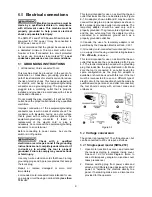
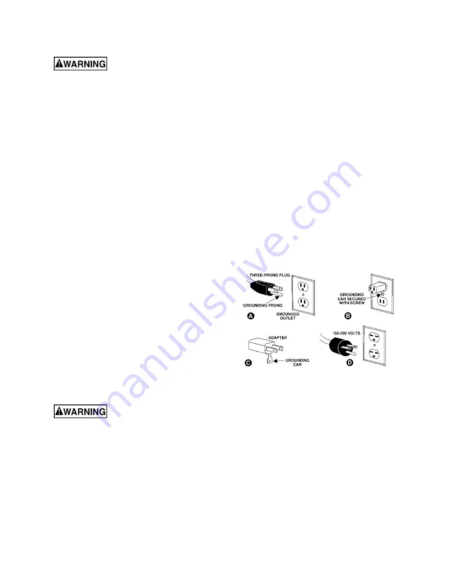
This tool is intended for use on a circuit that has an 
outlet that looks like the one illustrated in 

A, 

Figure 

6-1. An adapter, shown in 

B

 and 

C

, may be used to 

connect this plug to a 2-pole receptacle as shown in 

B

 if a properly grounded outlet is not available. The 

temporary adapter should be used only until a 
properly grounded. The green-colored rigid ear, lug, 
and the like, extending from the adapter must be 
connected to a permanent ground such as a 
properly grounded outlet box. 

In Canada, the use of a temporary adaptor is not 
permitted by the Canadian Electrical Code, C22.1. 

3.  Grounded, cord-connected tools intended for use 
on a supply circuit having a nominal rating between 

150 - 250 volts

, inclusive: 

This tool is intended for use on a circuit that has an 
outlet that looks like the one illustrated in 

D,

 Figure 

6-1. The tool is intended to be used with a grounding 
plug that looks like the plug illustrated in 

D

. Make 

sure the tool is connected to an outlet having the 
same configuration as the plug. No adapter is 
available or should be used with this tool. If the tool 
must be reconnected for use on a different type of 
electric circuit, the reconnection should be made by 
qualified service personnel; and after reconnection, 
the tool should comply with all local codes and 
ordinances. 


Figure 6-1 

6.2

  Voltage conversion 

The grinder is prewired for 115 volt input power, but 
can be converted to 230 volt input, as follows. 

6.2.1

 Single speed model (SWG-272) 

1.  Open motor junction box cover, and reconnect 

the leads according to diagram inside cover. 
See 

sect. 14.0

 for similar diagram. (Note: In 

case of discrepancy, diagram on junction cover 
takes precedence.) 

2.  Remove existing plug from power cable and 

attach a UL/CSA listed plug designed for 230V 
power; or “hardwire” the machine directly to a 
panel. If hardwiring make sure a disconnect is 
provided for the operator. 

Summary of Contents for 577400

Page 1: ...t Grinder Model SWG 272 SWG 272VS JET 427 New Sanford Road LaVergne Tennessee 37086 Part No M 577400 Ph 800 274 6848 Edition 1 11 2020 www jettools com Copyright 2020 JET Variable speed model Single speed model shown with platen assembly This pdf document is bookmarked ...

Page 2: ... not operate the machine with the guards removed 5 Avoid dangerous working environments Do not use stationary machine tools in wet or damp locations Keep work areas clean and well lit 6 Avoid accidental starts by being sure that the start switch is in the OFF position before plugging in the machine 7 Never leave the machine running while unattended The machine shall be shut off whenever it is not ...

Page 3: ...ver use an abrasive which shows backing nicks or cuts on the surface or edge or damage due to creasing or poor handling 10 Always present the workpiece to the wheel while resting the workpiece firmly on the table Failure to do so could result in damage to the workpiece or throwing of the workpiece off the wheel 11 Safety shoes which comply with ANSI Z41 1 shall be worn See Figure C 12 Personal hea...

Page 4: ...structed to provide consistent long term operation if used in accordan ce with the instructions set forth in this document This document is not however intended to be an exhaustive guide to grinding operations or choice of metal stock Consult machinery handbooks web forums or experienced users if additional information is needed Safety of user and bystanders must always be first priority If there ...

Page 5: ...t 13 9 4 Additional servicing 13 10 0 Optional accessories 13 11 0 Troubleshooting SWG series Square Wheel Grinders 14 12 0 Replacement Parts 14 12 1 1 SWG 272 Square Wheel Belt Grinder Exploded View 15 12 1 2 SWG 272 Square Wheel Belt Grinder Parts List 16 12 2 1 SWG 272 Motor Assembly Parts List and Exploded View 17 12 3 1 SWG 272 Push Button Switch Assembly Parts List and Exploded View 18 12 4 ...

Page 6: ...mission 2 80 dB at 3ft without load Base Footprint L x W 35 7 16 x 16 15 16 in 900 x 430 mm Mounting hole dimensions Dia 7 16 in 11mm Belt Grinder Belt included L x W 50 grit 72 x 2 in 1829 x 50 8 mm Belt speed SFPM 4 600 2 000 6 200 Contact wheels included Dia x W 1 1 2 x 2 in 38 x 50 8 mm smooth 3 x 2 in 76 2 x 50 8 mm smooth 8 x 2 in 203 2 x 50 8 mm serrated Dust port diameter 3 in 76 2 mm Main...

Page 7: ...he user to make a better estimation of the hazards and risks involved only L length W width H height Dia diameter The specifications in this manual were current at time of publication but because of our policy of continuous improvement JET reserves the right to change specifications at any time and without prior notice without incurring obligations 4 1 Hole spacing SWG 272 272VS Figure 4 1 All dim...

Page 8: ...ome are accessed behind the side panel to accept fasteners for this purpose Sect 4 1 shows the hole patterns An optional JET stand is available for this machine See sect 10 0 Use the 4 holes in front of the motor to secure to this stand 5 2 Installing work rest The work rest mounts to a channel on left side of head casting See Figure 5 2 Attach work rest with adjustable handle Slide work rest inwa...

Page 9: ...at have 3 prong grounding plugs and 3 pole receptacles that accept the tool s plug Repair or replace damaged or worn cord immediately 2 Grounded cord connected tools intended for use on a supply circuit having a nominal rating less than 150 volts This tool is intended for use on a circuit that has an outlet that looks like the one illustrated in A Figure 6 1 An adapter shown in B and C may be used...

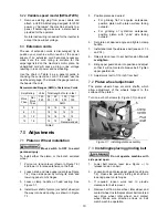
Page 10: ...per guard see Figure 7 2 Open side panel by turning its knob and lowering panel on its hinges 3 Loosen clamp handle on head casting See Figure 7 1 4 Install pivot shaft of platen or shaft of wheel all the way into head casting as shown in Figure 7 1 5 Position platen as desired For grinding flat or angular workpieces position platen with platen surface facing outward For grinding of cylindrical wo...

Page 11: ...ll increments and allow belt to respond to the changes 4 Close side panel and secure by turning knob on panel Lower upper belt guard and secure with knob 5 Turn on grinder Check belt tracking belt should remain centered on contact wheel Make further adjustments as needed according to step 3 6 If belt still does not track properly increase belt tension and repeat steps 1 through 5 Figure 7 3 Belt t...

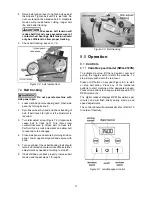
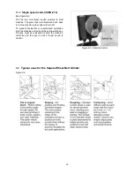
Page 12: ...h back in to stop machine green light will turn off To prevent accidental or unauthorized operation stop the machine and pull out the yellow safety key The key must be reinserted to start the machine Push key all the way in until a snap sound is heard Figure 8 2 standard control 8 2 Typical uses for the Square Wheel Belt Grinder Figure 8 3 ...

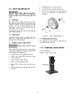
Page 13: ...ent Move switch to OFF to avoid personal injury If the contact wheel becomes worn a new contact wheel can be assembled to the existing wheel shaft and bearings refer to Figure 9 1 1 Lower tension lever to release belt tension 2 Loosen upper guard knob and swing guard back for clearance 3 Loosen handle on head casting 4 Remove contact wheel assembly 5 Remove the C retaining ring 6 4 from wheel shaf...

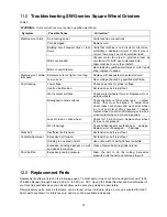
Page 14: ...ned To adjust drive wheel loosen set screws and move drive wheel in or out on motor shaft as required To adjust contact wheel loosen shaft clamping screw and move contact wheel in or out as required Lack of crown on drive wheel Check for 1 16 inch crown Replace drive wheel if crown is not present Worn bearings Check all bearings for overheating or damage Replace worn or damaged bearings Slack belt...

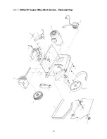
Page 15: ...15 12 1 1 SWG 272 Square Wheel Belt Grinder Exploded View ...

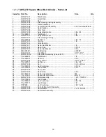
Page 16: ...5 16 x 1 1 19 SWG272 19 Nylon Flat Washer 5 16 3 20 BB 6200ZZ Ball Bearing 6200ZZ 2 21 SWG272 21 Idler Wheel OD3 x W2 1 SWG272 21E Idler Wheel Assembly include 20 1 22 TS 0680021 Flat Washer 1 4 1 23 TS 0561021 Hex Nut 5 16 3 24 SWG272 24 Drive Wheel OD10 x B7 8 1 25 TS 0267041 Set Screw 1 4 x 3 8 1 26 SWG272 26 Key 5 x 5 x 40 mm 1 27 TS 0051091 Hex Cap Screw 5 16 x 2 1 28 TS 0720081 Lock Washer 5...

Page 17: ...ssembly 4P 1 33 9 SWG272 339 Dust Cover 1 33 10 F001235 Phillips Pan Head Machine Screw 10 24 x 1 4 10 33 11 SWG272 3311 Cooling Fan 1 33 12 SWG272 3312 Fan Cover 1 33 13 SWG272 3313 Junction Box Seat 1 33 14 SWG272 3314 Terminal Block 1 33 15 F000233 Phillips Pan Head Machine Screw 10 24 x 1 2 2 33 16 F000231 Phillips Pan Head Machine Screw 10 24 x 3 8 1 33 17 SWG272 3317 Junction Box Cover 1 33 ...

Page 18: ... Bracket 1 38 2 SWG272 382 Switch Box 1 38 3 SWG272 383 Strain Relief 2 38 4 SWG272 384 Power Cord 16AWG x 3C 1 38 5 SWG272 385 Motor Cord 16AWG x 3C 1 38 6 TS 081C022 Phillips Pan Head Machine Screw 10 24 x 3 8 2 38 7 SWG272 387 Push Button Switch 1 JDC 500022 SC Safety Key not shown 1 38 8 SWG272 388 Pan Head Tapping Screw M3 x 20 4 ...

Page 19: ...19 12 4 1 SWG 272VS Square Wheel Belt Grinder Exploded View ...

Page 20: ... 16 x 1 1 19 SWG272 19 Nylon Flat Washer 5 16 3 20 BB 6200ZZ Ball Bearing 6200ZZ 2 21 SWG272 21 Idler Wheel OD3 x W2 1 SWG272 21E Idler Wheel Assembly include 20 1 22 TS 0680021 Flat Washer 1 4 1 23 TS 0561021 Hex Nut 5 16 3 24 SWG272 24 Drive Wheel OD10 x B7 8 1 25 TS 0267041 Set Screw 1 4 x 3 8 1 26 SWG272 26 Key 5 x 5 x 40 mm 1 27 TS 0051091 Hex Cap Screw 5 16 x 2 1 28 TS 0720081 Lock Washer 5 ...

Page 21: ...ll Bearing 6203ZZ 1 33 6 SWG272 336 End Cover 1 33 7 IBG8 42 Screw M5 x 205 4 33 9 SWG272 339 Dust Cover 1 33 10 F001235 Phillips Pan Head Machine Screw 10 24 x 1 4 6 33 11 SWG272 3311 Cooling Fan 1 33 12 SWG272 3312 Fan Cover 1 33 13 SWG272 3313 Junction Box Seat 1 33 14 SWG272 3314 Terminal Block 1 33 15 F000233 Phillips Pan Head Machine Screw 10 24 x 1 2 2 33 16 F000231 Phillips Pan Head Machin...

Page 22: ...VS 388 Toggle Switch 4P 1 38 9 SWG272VS 389 Cover Plate 1 38 10 SWG272VS 3810 Nut 1 38 11 SWG272VS 3811 Dustproof Rubber Sleeve 1 38 12 SWG272VS 3812 Safety Cover for Toggle Switch 1 38 13 SWG272VS 3813 Control Panel w Digital Readout includes 15 1 38 14 F001472 Flat Head Screw M4 0 7 x 6 4 38 15 SWG272VS 3815 Panel Decal 1 38 16 F000231 Phillips Pan Head Machine Screw 10 24 x 3 8 4 38 17 F001235 ...

Page 23: ...asting 1 4 2 SWG272 402 Tension Lever 1 4 3 SWG272 403 Nylon Tipped Set Screw M8 x 20 1 4 4 SWG272 404 Idler Pulley Shaft 1 4 5 SWG272 405 Tracking Leader Assembly 1 4 6 SWG272 406 Nylon Flat Washer 3 8 2 4 7 SWG272 407 Hand Knob 3 8 x 3 1 4 8 TS 0640091 Nylon Lock Hex Nut 3 8 16 1 4 9 SWG272 409 Roll Pin 5 x 38 mm 1 4 10 SWG272 410 Knob 35 3 8 1 ...

Page 24: ...5 1 SWG272 501 Platen 1 5 2 F010725 Socket HD Flat Screw 5 16 18 x 5 8 2 5 3 SWG272 503 Contact Wheel Shaft 2 5 4 BB 6200ZZ Ball Bearing 6200ZZ 5 5 5 SWG272 505 Contact Wheel 3 x 2 70 Duro 1 5 6 TS 0680061 Flat Washer 1 2 2 5 7 TS 0561051 Hex Nut 1 2 20 2 5 8 SWG272 508 Contact Wheel 1 1 2 x 2 70 Duro 1 ...

Page 25: ...ly all models Parts List and Exploded View Index No Part No Description Size Qty 6 1 SWG272 601 Contact Wheel 8 x2 Serrated 90Duro 1 6 2 SWG272 602 Shaft 1 6 3 BB 6203VV Ball Bearing 6203VV 2 6 4 F006045 C Retaining Ring Ext S17 1 ...

Page 26: ...and Exploded View Index No Part No Description Size Qty 40 1 SWG272 4001 Rail 1 40 2 SWG272 4002 Channel 1 40 3 SWG272 4003 Scoop 1 40 4 SWG272 4004 Hand Knob 5 16 x 1 2 40 5 TS 0207021 Socket Cap Screw 1 4 20 x 1 2 2 40 6 TS 0720071 Lock Washer 1 4 2 ...

Page 27: ...27 13 0 Electrical Connections 13 1 Wiring diagram for SWG 272 13 2 Wiring diagram for SWG 272VS ...

Page 28: ...needed JET has Authorized Service Centers located throughout the United States For the name of an Authorized Service Center in your area call 1 800 274 6846 or use the Service Center Locator on the JET website More Information JET is constantly adding new products For complete up to date product information check with your local distributor or visit the JET website How State Law Applies This warra...

Reviews: