background image


GB - ENGLISH 

Operating Instructions 


Dear Customer, 

Many thanks for the confidence you have shown in us with the purchase  of  your new JET-machine. This manual has been 
prepared for the owner and operators of a JET 701  bench top  mortiser  to promote safety during installation, operation and 
maintenance procedures. Please read and understand the information contained in these operating instructions and the 
accompanying documents. To obtain maximum life and efficiency from your machine, and to use the machine safely, read this 
manual thoroughly and follow instructions carefully. 


…Table of Contents 

1. Declaration of conformity


2. Warranty


3.  Safety


Authorized use 
General safety notes 
Remaining hazards 

4. Machine specifications


Technical data 
Noise emission 
Contents of delivery 
Machine description 

5. Transport and start up


Transport and installation 
Assembly 
Mains connection 
Starting operation 

6. Machine operation 

7. Setup and adjustments 

Installing chisel and bit 
Setting the depth stop 
Installing the chuck extension 
Handle position adjustment 
Rotating column 
Sharpening chisel and bit 

8. Maintenance and inspection 

9. Trouble shooting


10. Available accessories


1.  Declaration of conformity 

On our own responsibility we hereby 
declare that this product complies with 
the regulations* listed on page 2. 
Designed in consideration with the 
standards**. 


2.  Warranty 

The Seller guarantees that the 
supplied product is free from material 
defects and manufacturing faults. This 
warranty does not cover any defects 
which are caused, either directly or 
indirectly, by incorrect use, 
carelessness, accidental damage, 
repair, inadequate maintenance or 
cleaning and normal wear and tear. 

Guarantee and/or warranty claims 
must be made within twelve months 
from the date of purchase (date of 
invoice). Any further claims shall be 
excluded. 

This warranty includes all guarantee 
obligations of the Seller and replaces 
all previous declarations and 
agreements concerning warranties. 

The warranty period is valid for eight 
hours of daily use. If this is exceeded, 
the warranty period shall be reduced 
in proportion to the excess use, but to 
no less than three months. 

Returning rejected goods requires the 
prior express consent of the Seller and 
is at the Buyer’s risk and expense. 

Further warranty details can be found 
in the General Terms and Conditions 
(GTC). The GTC can be viewed at 
www.jettools.com or can be sent by 
post upon request. 

The Seller reserves the right to make 
changes to the product and 
accessories at any time. 


3.  Safety 

3.1 Authorized use 

This mortiser is designed for mortising 
wood and similar materials only. 
Machining of other materials is not 
permitted and may be carried out in 
specific cases only after consulting 
with the manufacturer.  

The proper use also includes 
compliance with the operating and 
maintenance instructions given in this 
manual. 

The machine must be operated only 
by persons familiar with its operation 
and maintenance and who are familiar 
with its hazards. 

The required minimum age must be 
observed. 

The machine must only be used in a 
technically perfect condition. 

When working on the machine, all 
safety mechanisms and covers must 
be mounted. 

In addition to the safety requirements 
contained in these operating 
instructions and your country’s 
applicable regulations, you should 
observe the generally recognized 
technical rules concerning the 
operation of woodworking machines. 

Any other use exceeds authorization. 
In the event of unauthorized use of the 
machine, the manufacturer renounces 
all liability and the responsibility is 
transferred exclusively to the operator.  


3.2 General safety notes 

Woodworking machines can be 
dangerous if not used properly. 
Therefore the appropriate general 
technical rules as well as the following 
notes must be observed. 

Read and understand the entire 
instruction manual before attempting 
assembly or operation. 

Keep this operating instruction close 
by the machine, protected from dirt 
and humidity, and pass it over to the 
new owner if you part with the tool. 

No changes to the machine may be 
made. 

Summary of Contents for 701

Page 1: ...d agreements concerning warranties The warranty period is valid for eight hours of daily use If this is exceeded the warranty period shall be reduced in proportion to the excess use but to no less than three months Returning rejected goods requires the prior express consent of the Seller and is at the Buyer s risk and expense Further warranty details can be found in the General Terms and Condition...

Page 2: ...ze of the work piece must be observed Do not remove chips and work piece parts until the machine is at a standstill Do not stand on the machine Connection and repair work on the electrical installation may be carried out by a qualified electrician only Have a damaged or worn power cord replaced immediately Make all machine adjustments or maintenance with the machine unplugged from the power source...

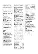
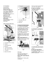
Page 3: ...ing in an environmentally friendly manner Clean all rust protected surfaces with a mild solvent Mount operating handle Insert the operating handle G Fig 4 into the bracket H Lock the lock handle F Fig 4 The operating handle can be mounted on either the left or right hand side of the mortiser Fig 5 To change place remove knob A Fig 5 washer B and spring C Mount tool holder The 701 bench top mortise...

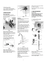
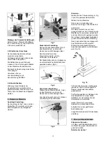
Page 4: ... fast enough to prevent burning at the tip of the drill bit but not so fast as to cause the machine to stall The different rates of feed for different woods must be learned by experience After the first cut the work piece is moved The direction of movement must allow the chips to clear freely Fig 10 Fig 10 When cutting deep mortises make the cut in several stages of approx 25mm each to allow chips...

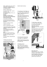
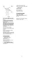
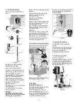
Page 5: ... 12 Tighten the lock handle A 7 3 Installing the Chuck Extension If you plan to install a bit with a short shank you need to install the chuck extension D Fig 13 Place a 12mm open spanner on the motor spindle C and use the chuck key to unscrew the chuck B Attach the spindle extension to the chuck and reinstall Fig 13 7 4 Handle position adjustment The handle can be repositioned Pulling out the hub...

Page 6: ...pair and maintenance work on the electrical system may only be carried out by a qualified electrician 9 Trouble shooting Motor doesn t start No electricity check mains and fuse Defective switch motor or cord consult an electrician Chisel clogged with chips Clearance chisel to bit not enough see chapter 7 1 chips cannot clear the chisel observe chisel slot and working order Burned wood Feed too slo...

Page 7: ...sprüche müssen innerhalb von 12 Monaten ab dem Verkaufsdatum Rechnungsdatum geltend gemacht werden Weitergehende Ansprüche sind ausgeschlossen Die vorliegende Garantie umfasst sämtliche Garantieverpflichtungen seitens des Verkäufers und ersetzt alle früheren Erklärungen und Vereinbarungen betreffend Garantien Die Garantiefrist gilt für eine tägliche Betriebszeit von 8 Stunden Wird diese überschrit...

Page 8: ...n die laufende Maschine greifen Die laufende Maschine nie unbeaufsichtigt lassen Vor dem Verlassen des Arbeitsplatzes die Maschine ausschalten Halten Sie Unbeteiligte insbesondere Kinder vom Gefahrenbereich fern Benützen Sie die Maschine nicht in der Nähe von brennbaren Flüssigkeiten oder Gasen Beachten Sie die Brandmelde und Brandbekämpfungsmöglichkeiten z B Standort und Bedienung von Feuerlösche...

Page 9: ...en in der Werkstatt sind dabei ausreichend Die Aufstellfläche muss ausreichend eben und belastungsfähig sein Die Maschine kann sowohl auf einem belastbaren Tisch als auch auf dem Originalunterschrank festgeschraubt werden Festschrauben der Maschine Befestigen Sie die Maschine an den 4 Montagebohrungen A Fig 3 um ein Kippen sicher zu verhindern Fig 3 5 2 Montage Wenn Sie beim Auspacken einen Transp...

Page 10: ... 8 Fig 8 Druckrollen Einstellung Stellen Sie die Druckrollen M Fig 9 an das Werkstück so dass sich dieses noch seitlich bewegen lässt Zum Anstellen auf Lasche L drücken und Klemmgriff K festziehen Fig 9 Stemmen Stellen Sie den Tiefenanschlag A Fig 12 auf die gewünschte Bohrtiefe Starten Sie die Maschine Ziehen sie am Handhebel und stemmen Sie zügig in das Werkstück ACHTUNG Der Bohrvorschub muss sc...

Page 11: ...mmmeißel HINWEIS Der Schlitz des Stemmmeißels sollte nur nach links oder rechts zeigen Dadurch wird bei der Bearbeitung die Späneabfuhr nicht beeinträchtigt Der Stemmeißel sollte parallel zum Werkstück ausgerichtet sein 7 2 Bohrtiefenanschlag Einstellung Senken Sie den Bohrkopf D Fig 12 auf die gewünschte Bohrtiefe ab Fig 12 Setzen Sie den Bohrtiefenanschlag B mit dem Klemmhebel A fest 7 3 Montage...

Page 12: ...raturarbeiten muss die Maschine gegen Inbetriebnahme gesichert werden Netzstecker ziehen Der Wartungsumfang der Stemmmaschine beschränkt sich auf leichte Schmierung Routineeinstellungen und Stemmmeißel Nachschärfung Reinigen Sie die Maschine in regelmäßigen Zeitabständen Beschädigte Sicherheitseinrichtungen sofort ersetzen Anschlüsse und Reparaturen der elektrischen Ausrüstung dürfen nur von einer...

Page 13: ... mois suivant la date de la vente date de la facture Toute autre prétention est exclue La présente garantie comprend toutes les obligations de garantie incombant au vendeur et remplace toutes les déclarations et conventions antérieures en termes de garanties Le délai de garantie s applique pour une durée d exploitation de huit heures par jour Au delà le délai de garantie diminue proportionnellemen...

Page 14: ...ine de l humidité et ne jamais l exposer à la pluie Retirer les clous et autres corps étrangers de la pièce avant de débuter l usinage Travailler seulement avec des outils bien aiguisés Seulement usiner une pièce qui peut être bien posée sur la table Se tenir aux spécifications concernant la dimension maximale ou minimale de la pièce à usiner Ne pas enlever les copeaux et les pièces usinées avant ...

Page 15: ...achine Eliminer l emballage dans le respect de l environnement Enlever la protection antirouille avec un dissolvant Montage du levier Fixer le levier G Fig 4 dans le moyeu H avec la vis de blocage F Fig 4 Le levier peut être aussi bien monté à gauche qu à droite de la tête Fig 5 Pour le changer de côté retirer la vis de blocage A Fig 5 la rondelle B et le ressort C Montage du porte outil La mortai...

Page 16: ...a pièce REMARQUE Effectuer le perçage rapidement pour éviter des brûlures sur la surface mais ne pas stopper le moteur La vitesse d avance idéale pour chaque type de bois demande de l expérience Après le premier procédé de mortaisage déplacer la pièce latéralement Choisir la direction de travail de manière à ne pas gêner l évacuation des copeaux Fig 10 Fig 10 Effectuer les perçages profonds par ét...

Page 17: ...aisser la tête de perçage D Fig 12 à la profondeur demandée Fig 12 Déterminez la butée de profondeur B avec le levier de serrage A 7 3 Montage de la rallonge d arbre Pour les matoirs à tige courte utiliser la rallonge D Fig 13 jointe à la livraison Bloquer la broche du moteur C avec une clé à fourche de 12mm et desserrer le mandrin B avec la clé de mandrin Monter la rallonge sur le mandrin avant d...

Page 18: ...t Remplacer immédiatement les dispositifs de protection endommagés ou usés Tous travaux de branchement et de réparation sur l installation électrique doivent être exécutés uniquement par un électricien qualifié 9 Détecteur de pannes Moteur ne se met pas en route Pas de courant Vérifier le voltage Défaut au moteur bouton ou câble Contacter un électricien qualifié Mèche pour mortaiser bouchée Distan...

Reviews: