background image


4


Warning 

Wear eye protection. 

Always keep guards in place and in proper operating condition. Do not operate the machine without the 

guards for any reason. 

This disc/belt sander is intended to be used with wood and wood products only. Use of this disc/belt 

sander and a dust collector with metal products is a potential fire hazard. 

Support the workpiece adequately at all times during operation; maintain control of the work at all 

times. 

This disc/belt sander is designed and intended for use by properly trained and experienced 

personnel only.  If you are not familiar with the proper and safe operation of a disc/belt sander, do 

not use until proper training and knowledge have been obtained. 


REMOVE ADJUSTING KEYS AND WRENCHES.

  Form a habit of checking to see that keys and 

adjusting wrenches are removed from the machine before turning it on. 


KEEP THE WORK AREA CLEAN

.  Cluttered areas and benches invite accidents. 


DON’T USE IN A DANGEROUS ENVIRONMENT.

  Don’t use power tools in damp or wet locations, 

or expose them to rain.  Keep work area well lighted. 


KEEP CHILDREN AWAY.

  All visitors should be kept a safe distance from the work area. 


MAKE THE WORKSHOP KIDPROOF

 with padlocks, master switches, or by removing starter keys. 


DON’T FORCE THE MACHINE.

  It will do the job better and safer at the rate for which it was 

designed. 


USE THE RIGHT TOOL.

  Don’t force a machine or attachment to do a job for which it was not 

designed. 


USE THE PROPER EXTENSION CORD.

  Make sure your extension cord is in good condition.  When 

using an extension cord, be sure to use one heavy enough to carry the current your machine will 
draw.  An undersized cord will cause a drop in the line voltage resulting in power loss and 
overheating. The table following shows the correct size to use depending on the cord length and 
nameplate ampere rating.  If in doubt, use the next heavier gauge.  Remember, the smaller the gauge 
number, the heavier the cord. 


Volts


Total Length of Cord in Feet


120V 25 

50 

100  150 


AWG


 16  16  14 12 


WEAR PROPER APPAREL.

  Do not wear loose clothing, gloves, neckties, rings, bracelets, or other 

jewelry which may get caught in moving parts.  Nonslip footwear is recommended.  Wear protective 
hair covering to contain long hair. 


ALWAYS USE SAFETY GLASSES.

  Also use face or dust masks if the cutting operation is dusty.  

Everyday eyeglasses only have impact resistant lenses; they are not safety glasses. 


DON’T OVERREACH.

  Keep proper footing and balance at all times. 


MAINTAIN TOOLS WITH CARE.

  Keep tools sharp and clean for best and safest performance.  

Follow instructions for lubricating and changing accessories. 

Summary of Contents for 708595

Page 1: ...htop Disc Belt Sander Model JSG 96 shown with optional closed stand 708597 JET 427 New Sanford Road LaVergne Tennessee 37086 Part No M 708595 Ph 800 274 6848 Revision H 10 2015 www jettools com Copyri...

Page 2: ...nal action needed JET has Authorized Service Centers located throughout the United States For the name of an Authorized Service Center in your area call 1 800 274 6846 or use the Service Center Locato...

Page 3: ...g Belt Replacement 11 Belt Tracking Adjustment 12 Disc Table Adjustment 12 Sanding Disc Replacement 13 Center Point 13 On Off Switch 13 Dust Collection 14 Maintenance 14 Lubrication 14 Optional Access...

Page 4: ...hes or by removing starter keys DON T FORCE THE MACHINE It will do the job better and safer at the rate for which it was designed USE THE RIGHT TOOL Don t force a machine or attachment to do a job for...

Page 5: ...sures varies depending on how often you do this type of work To reduce your exposure to these chemicals work in a well ventilated area and work with approved safety equipment such as those dust masks...

Page 6: ...wire extension cords that have three prong grounding plugs and three pole receptacles that accept the tool s plug Repair or replace a damaged or worn cord immediately 115 Volt Operation As received fr...

Page 7: ...15V 60Hz 1Ph 4P Belt Speed SFPM 2 258 Disc Speed RPM 1 725 Overall Dimensions 16 Lx31 Wx28 3 4 H Net Weight approx 91 Lbs Gross Weight approx 100 Lbs The above specifications were current at the time...

Page 8: ...n of the disc belt sander Failure to comply may cause serious injury Consult the breakdown drawings at the back of this manual if further clarification is needed on assembly instructions Open Stand As...

Page 9: ...en stand uses four 3 8 x3 hex cap bolts four 3 8 lock washers and eight 3 8 flat washers and four hex nuts provided with the stand 2 Mount the sanding disc table assembly A Fig 1 to the sander base In...

Page 10: ...e travels parallel to the belt Loosen the two socket head cap screws at the bottom of the table which hold the table and left trunnion in place to adjust the distance 4 Always maintain a gap of approx...

Page 11: ...1 Disconnect the machine from the power source 2 Remove the handle A Fig 8 3 Release two latches B Fig 8 and open the doors 4 Pivot the trunnion assembly A Fig 9 out of the way 5 Release the belt tens...

Page 12: ...ncy to track right of center turn the adjusting knob clockwise until the belt tracks in the center 5 Secure the tracking lock by pushing the lever down Note when tightening the tracking lock the belt...

Page 13: ...sc Note The belt table can be removed and the disc table can be used in its place There are two holes in the base below the sanding belt that will accommodate the disc table s support rod and locking...

Page 14: ...Tighten the wing nut 3 Push the gate D Fig 16 down to shut off air suction to the disc Lift the gate to open the air suction to the disc Maintenance Keep the exposed metal surface of the disc table cl...

Page 15: ...ine should be pointing in the same direction Sanded edge not square Table not square to sanding belt Use a square to adjust table to sanding belt Miter slot not parallel to sanding belt Use a square t...

Page 16: ...16 Disc Sander Assembly Breakdown...

Page 17: ...port w Scale 1 24 TS 0680031 Flat Washer 5 16 2 25 TS 0051021 Hex Head Screw 5 16x5 8 2 26 JSG96 126 Lock Handle 1 27 JSG96 127 Screw 1 4x3 8 1 28 JSG96 128 Pointer 1 29 TS 0270031 Set Screw 5 16x3 8...

Page 18: ...mall Running Capacitor 1 59 JSG96 159 Holder Big Starting Capacitor 1 60 JSG96 160 Plate 1 JSG96 MGA Miter Gauge Assembly Items 38 46 thru 52 1 JSG96 CGA Circle Gauge Assembly Items 42 thru 45 1 items...

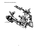
Page 19: ...19 Belt Sander Assembly Breakdown See Disc Sander Breakdown...

Page 20: ...7 JSG96 227 Lock Nut 3 8 1 28 JSG96 228 Roll Pin 4x20 1 29 JSG96 229 Support Bracket 1 30 JSG96 230 Micro Adjusting Seat 1 31 TS 0207021 Hex Socket Cap Screw 1 4x1 2 6 32 JSG96 232 Screw 1 33 JSG96 23...

Page 21: ...escription Size Qty 61 JSG96 261 Serrated Plate 2 62 JSG96 262 Phillips Tap Screw M3x10 4 63 JSG96 263 Lock Washer 1 64 JSG96 264 Set Screw 1 4x1 1 2 1 JSG96 HK Hardware Kit Includes items marked with...

Page 22: ...05 Carriage Bolt 5 16x5 8 16 6 JSG96 406 Lock Nut w Flange 5 16 16 7 JSG96 407 Leveling Pad 4 8 TS 0561031 Hex Nut 3 8 13 9 TS 0680041 Flat Washer 3 8 17 10 TS 0060131 Hex Head Screw 3 8x3 4 11 JSG96...

Page 23: ...23 Closed Stand Assembly Optional...

Page 24: ...ock Nut M10x1 5 1 12 TS 0720091 Lock Washer 3 8 4 13 TS 0680041 Flat Washer 3 8 8 14 JSG96 314 Tool Shelf 1 15 TS 0060031 Hex Head Screw 3 8x3 4 1 16 JSG96 316 Washer 3 8x1 1 8 1 17 JSG96 317 JET Plaq...

Reviews: