background image

 20 

11.0

  Tracker kit 

Stock No.: PM2244-213 

Trackers  dramatically  reduce  tracking  adjustments 
of conveyor belts. They are already installed on your 
sander. The following information is for resetting or 
replacing  your  trackers,  should  that  become 
necessary.


1.  Disconnect power to sander. 

2.  Raise drum as high as it will go. 

3.  Turn  both  conveyor  take-up  screws  to  relieve 

conveyor belt tension and slide driven roller fully 
inward. 

4.  Remove the 2 bolts and loosen 2 wing screws 

holding conveyor table to sander base. 

5.  Lift  conveyor  table  and  slide  it  out  of  sander. 

Turn  conveyor  table  upside  down.  Be  careful 
not to damage conveyor belt. 

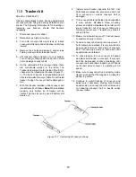
6.  On  the  underside  of  the  conveyor  table,  there 

are  U-channels  welded  to  the  table.  The 
Tracker is positioned on the inside of the first U-
channel on the infeed side of sander (Figure 11-
1). The back of tracker is magnetized and will 
stick to side wall of conveyor table. Do not install 
tracker if edge of conveyor belt is damaged or 
torn.  

7.  With  first  tracker  installed,  slide  conveyor  belt 

into bottom slot of tracker. 

Note:

 When installed 

properly,  only  bottom  lip  of  tracker  will  be 
visible. The top slot can be used if bottom slot 
wears out. 

8.  Install  second  tracker  opposite  the  first.  Use 

both trackers unless the second one does not 
fit  in  conveyor  or  unless  conveyor  belt  is 
damaged. 

9.  Turn conveyor table right-side up and reposition 

it  onto  sander.  Re-attach  three  mounting 
screws and tighten. 

Caution:

 Be careful not to 

knock  tracker(s)  out  of  conveyor  table  when 
turning  conveyor  over.  Trackers  may  break  if 
allowed to fall. 

10.  Make sure all switches are off. Connect power 

to sander and plug in motor. 

11.  Tension conveyor belt using take-up screws. If 

both trackers are installed, it is very important to 
have equal tension on both sides of conveyor 
belt.  Turn  take-up  screws  on  both  sides  until 
equal tension is obtained. 

12.  To check tension, turn on conveyor full speed 

and place both hands on conveyor. If conveyor 
belt  can  be  stopped,  continue  tensioning  until 
conveyor belt cannot be stopped by both hands 
on  the  belt  while  conveyor  is  operating  at  full 
speed. 

13.  Make sure conveyor belt runs smoothly inside 

tracker slot and that the magnet is holding the 
tracker in position. 

14.  Continue  to  watch  tracking  of  conveyor  and 

adjust  only  if  necessary,  making  sure  to  keep 
equal tension on conveyor belt at all times and 
not  allowing  conveyor  belt  to  buckle  under 
conveyor table. 


Figure 11-1:  Underside of conveyor shown 


Summary of Contents for 723540B

Page 1: ...ls JWDS 2244 JWDS 2550 JET 427 New Sanford Road LaVergne Tennessee 37086 Part No M 723540B Ph 800 274 6848 Edition 2 03 2019 www jettools com Copyright 2018 JET Model JWDS 2550 shown with optional clo...

Page 2: ...ower source 14 Remove adjusting keys and wrenches Form a habit of checking to see that keys and adjusting wrenches are removed from the machine before turning it on 15 Keep safety guards in place at a...

Page 3: ...on safety precautions general operating procedures maintenance instructions and parts breakdown Your machine has been designed and constructed to provide consistent long term operation if used in acco...

Page 4: ...tenance 18 10 1 Cleaning and lubrication 18 10 2 Drum maintenance 18 10 3 Conveyor belt replacement 19 10 4 Commutator brush inspection 19 10 5 Additional servicing 19 11 0 Tracker kit 20 12 0 Abrasiv...

Page 5: ...JWDS 2244 2550 Exploded View 36 15 6 2 Depth Stop Assembly for JWDS 2244 2550 Parts List 36 15 7 1 OPTIONAL Closed Stand Assembly for JWDS 2550 Exploded View 37 15 7 2 OPTIONAL Closed Stand Assembly f...

Page 6: ...r 50 F 250VAC Conveyor motor type totally enclosed DC Horsepower 1 30 HP 25 W Phase 1 Voltage 115 V Listed FLA full load amps 0 6 A Motor speed 54 RPM On off switch Toggle with safety key Power transf...

Page 7: ...8 1 4 in 113 x 70 x 71 75 cm Shipping carton open stand OPTIONAL LxWxH 38 x 20 x 4 1 2 in 96 5 x 50 8 x 11 4 cm 44 x 20 x 4 1 2 in 112 x 50 8 x 11 4 cm Shipping carton closed stand OPTIONAL LxWxH 40 9...

Page 8: ...illustration below shows the major components and features of the JWDS 2244 2550 Sanders These are referenced throughout the manual and will help to familiarize you with the operation and functions o...

Page 9: ...ce and safety instructions 6 1 Shipping contents Drum Sander Figure 6 1 1 Sander with conveyor table A 1 Height adjust handle B 1 Hose hanger C 2 Socket hd cap screw M6x12 C1 2 Flat washer 6mm C2 1 Op...

Page 10: ...anger C with screws and washers C1 C2 6 6 Folding infeed outfeed tables OPTIONAL See Figure 6 3 The sander must be bolted to the stand or a work table when using these table extensions Maximum working...

Page 11: ...ion hose to the port with a hose clamp Figure 6 5 and connect to a high volume dust collector minimum 550 CFM Note Dryer vent hose is not acceptable for this purpose Keep hose clear of conveyor area b...

Page 12: ...n or breakdown grounding provides a path of least resistance for electric current to reduce the risk of electric shock This tool is equipped with an electric cord having an equipment grounding conduct...

Page 13: ...lt Adjustment is performed by zeroing the scale 1 Unplug sander from power source 2 With an abrasive strip on drum lower drum to where it just contacts top of conveyor belt Note Make sure drum not jus...

Page 14: ...re made while conveyor belt is running 1 Make sure proper belt tension has been achieved see sect 8 5 1 2 Turn on conveyor and set to maximum speed Watch for tendency of conveyor belt to drift to one...

Page 15: ...of scrap wood approximately 6 wide by 30 to 40 long through the sander sideways so that end of board extends past outboard side of drum 2 Without changing drum height rotate board 180 and sand the sam...

Page 16: ...ate of conveyor belt NOTE The use of a carrier or backer board not provided is recommended for cuts 1 16 or less This is a flat board usually of wood or MDF slightly larger than the workpiece and of e...

Page 17: ...maple for example which can be damaged if fed through a planer Learning how to use its adjustments and controls will allow you to fine tune the machine for maximum results The best results come from e...

Page 18: ...the wood on the final one or two passes 10 0 User maintenance Before doing maintenance on the machine disconnect it from the electrical supply pull out the plug unless indicated otherwise Failure to c...

Page 19: ...ween roller and straightedge Step 2 Now repeat Step 1 on right inboard side of conveyor Compare the measurements from side to side If they are not equal loosen one of the brackets that hold the roller...

Page 20: ...op slot can be used if bottom slot wears out 8 Install second tracker opposite the first Use both trackers unless the second one does not fit in conveyor or unless conveyor belt is damaged 9 Turn conv...

Page 21: ...cept stains evenly This will vary by type of wood Oak for example is susceptible to burnishing because of its open pores 12 2 Cleaning abrasive strips Regularly clean the abrasive strip on the drum wi...

Page 22: ...t fuse or circuit breaker Loud repetitive noise or vibration coming from machine Fasteners loose Inspect fasteners and tighten where needed Motor fan is hitting cover Tighten fan or shim fan cover Mac...

Page 23: ...feed rate Dirty or worn conveyor belt Replace conveyor belt Ripples in sanded surface A Non uniformly spaced ripples B Uniformly spaced ripples A Uneven feed rate Conveyor belt slipping see above Boar...

Page 24: ...Premium Ready To CutTM Abrasive Strip 220 Grit 14 wraps For JWDS 2550 723550OS Open Stand for JWDS 2550 723544CS Closed Stand for JWDS 2550 723551 Folding Infeed Outfeed Tables for JWDS 2550 723552 Di...

Page 25: ...33 30 29 2 39 32 38 30 29 31 37 35 32 34 34 38 39 33 20 21 45 40 46 47 49 43 41 42 44 41 48 24 25 27 26 26 27 E 23 50 51 68 51 70 69 67 72 G F 85 86 87 88 73 79 74 78 77 76 71 75 E 83 84 102 99 G 51...

Page 26: ...5 PM2244 139 Rubber Cushion Re 17A 1 26 F010408 Socket Set Screw M8 1 25P x 10L 2 27 Coupling Re 17A 2 28 TS 1502011 Socket Head Cap Screw M5 0 8P x 8L 1 29 PM2244 125 Compression Spring 4 30 TS 15500...

Page 27: ...M8 1 25P x 6L 1 85 JWDS2244 185 Motor Plate 1 86 JWDS1632 157 Oilite Washer 4 87 TS 1550061 Flat Washer 8 2 x 23 x 2T 4 88 TS 1541031 Nylon Lock Hex Nut M8 1 25P 4 89 JWDS1836 154 Motor 1 75HP 115V 6...

Page 28: ...28 Index No Part No Description Size Qty JWDS1632 197 Left Parallel Adjust Label not shown 1 JWDS1632 198 Right Parallel Adjust Label not shown 1 LM000238 Warning Label not shown 1...

Page 29: ...includes 1 thru 9 1 TS 1503021 Socket Head Cap Screw M6 1 0P x 10L 4 2 TS 1550041 Flat Washer 6 5 x 13 x 1T 4 3 TS 1540031 Hex Nut M5 0 8P 1 4 JWDS2244 504 Upper Bracket 1 5 JWDS2244 505 Lower Bracket...

Page 30: ...30 15 3 1 JWDS 2244 2550 Conveyor Table Assembly Exploded View 1 3 2 11 4 12 21 22 7 8 9 10 15 2 13 14 15 1 20 20 24 7 7 23 9 16 17 18 19 16 17 18 19 9 9 20 5 25 6 15...

Page 31: ...t 1 26 JWDS1632 227 Conveyor Motor Label not shown 1 27 LM000236 Caution Label Table Lock not shown 1 15 3 3 JWDS 2550 Conveyor Table Assembly Parts List Index No Part No Description Size Qty 1 JWDS22...

Page 32: ...32 15 4 1 Open Stand Assembly for JWDS 2244 2550 Exploded View 1 11 10 8 8 7 9 9 10 8 7 7 5 1 7 7 8 8 1 11 9 10 3 4 10 9 8 7 2 6 1 5 2 3 4 3 4...

Page 33: ...mm 8 11 JWDS1632 311 Leveling Foot 4 JWDS2244 320 Hardware Package Open Stand includes 7 thru 11 15 4 3 OPTIONAL 723550OS Open Stand Assembly for JWDS 2550 Parts List Index No Part No Description Size...

Page 34: ...34 15 5 1 OPTIONAL Infeed Outfeed Tables for JWDS 2244 2550 Exploded View 1 2 4 2 10 6 7 7 3 11 10 7 3 6 6 12 2 3 4 6 7 13 1 3 5 2 5 9 8 2 9 8 5 3 5 8 9 10 3 2 12...

Page 35: ...4 413 Front Fixed Bracket 1 JWDS2244 420 Hardware Package Infeed Outfeed Tables includes 2 3 5 6 7 10 15 5 3 OPTIONAL 723551 Infeed Outfeed Tables for JWDS 2550 Parts List Index No Part No Description...

Page 36: ...3 Stop Nut 1 4 JWDS2244 604 Compression Spring 1 5 JWDS2244 605 Half Nut 1 6 TS 1550031 Flat Washer 5 2 x 16 x 1 4T 1 7 TS 1502031 Socket Head Cap Screw M5 0 8P x 12L 1 8 TS 1482051 Hex Cap Screw M6 1...

Page 37: ...3 JOSS S 242 Door Pivot 1 4 JOSS S 243 Compression Spring 1 5 6286482 E Retaining Ring Ext ETW 4 1 6 JWDS2550 706 Foam Strip 1 7 TS 1550061 Flat Washer 8 3 x 18 x 1 5T 14 8 TS 1504031 Socket Head Cap...

Page 38: ...0 Electrical Connections for JWDS 2244 2550 GM GM LOAD2 LINE2 LOAD1 LINE1 SANDING MOTOR TO BELT MOTOR White Black Black White White Black POWER IN White Black Green Green GROUND CIRCUIT BOARD POTENTIO...

Page 39: ...tional action needed JET has Authorized Service Centers located throughout the United States For the name of an Authorized Service Center in your area call 1 800 274 6846 or use the Service Center Loc...

Page 40: ...40 427 New Sanford Road LaVergne Tennessee 37086 Phone 800 274 6848 www jettools com...

Reviews: