13
EGH1740 | EGH1760
7.3 CHUCK AND CHUCK MOUNTING
(FOR D1-6 SPINDLE)
Use only high-speed chucks with these machines.
When fitting chucks or faceplate, ensure that spindle and
chuck tapers are thoroughly cleaned and that all cams lock
in the correct positions the first.
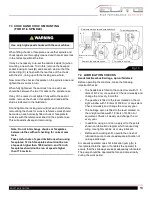
It may be necessary to re-set the camlock studs (A) when
mounting a new chuck. To do this, remove the hexagon
socket locking screws (B) and set each stud so that the
scribed ring (C) is flush with the rear face of the chuck -
with the slot - lining up with the locking screw hold.
Now mount the chuck or faceplate on the spindle nose and
tighten the six cams in turn.
When fully tightened, the cam lock line on each cam
should be between the two V marks on the spindle nose.
If any of the cams do not tighten fully within these limit
marks, remove the chuck or faceplate and readjust the
stud as indicated in the illustration.
Fit and tighten the locking screw (B) at each stud before
remounting the chuck for work. A reference mark should
be made on each correctly fitted chuck or faceplate to
coincide with the reference scribed on the spindle nose.
This will assist subsequent remounting.
Note: Do not interchange chucks or faceplates
between lathes without checking for correct cam
lock.
Take careful note of speed limitations when using
faceplates; 12 inch faceplates should not be run
at speeds higher than 1000 rev/min. and 14 inch
faceplates should not be run at speeds higher
than 770 rev/min.
Fig. 10
Cam lock line between arrows
Turn stud in one turn
Cam release datum
A C
B
Detail of camlock stud
ass’y
7.4 LUBRICATION CHECKS
Headstock/Gearbox/Carriage, Apron/Tailstock
Before operating the machine, make the following
important checks:
•
The headstock is filled to the correct level with 11.5
liters of R-32 oil, or equivalent. Check oil weekly and
change the oil every 6 months.
•
The gearbox is filled to the level marked on the oil
sight window with 1.8 liters of R-68 oil, or equivalent.
Check oil weekly and change the oil every year.
•
The carriage apron is filled to the level marked on
the oil sight window with 1.8 liters of R-68 oil or
equivalent. Check oil weekly and change the oil
every year.
•
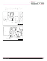
In addition, using an oil can, apply oil to the points
shown on lubrication diagram which require daily
oiling. Use light machine oil or way lubricant.
•
Before each working shift, operate the one shot
lubrication pump to ensure adequate lubrication of
carriage slideways.
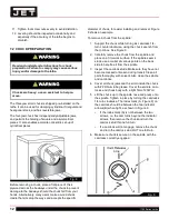
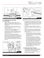
A manually operated one shot lubrication pump (A) is
incorporated into the apron. It enables the operator to
ensure that the slideways are kept adequately lubricated.
The pump should be operated before and occasionally
during the work period.
Turn stud out one turn
Reference mark on spindle nose and chuck
Summary of Contents for 892100
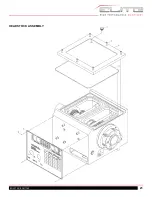
Page 21: ...21 EGH1740 EGH1760 HEADSTOCK ASSEMBLY ...
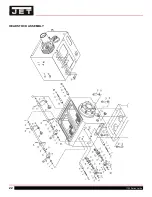
Page 22: ...22 1700 Series Lathe HEADSTOCK ASSEMBLY ...
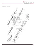
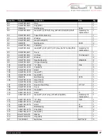
Page 23: ...23 EGH1740 EGH1760 HEADSTOCK ASSEMBLY ...
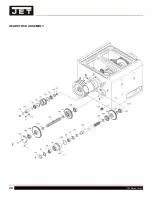
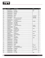
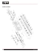
Page 24: ...24 1700 Series Lathe HEADSTOCK ASSEMBLY ...
Page 28: ...28 1700 Series Lathe GEARBOX ASSEMBLY ...
Page 29: ...29 EGH1740 EGH1760 GEARBOX ASSEMBLY ...
Page 33: ...33 EGH1740 EGH1760 APRON L H ASSEMBLY ...
Page 34: ...34 1700 Series Lathe APRON L H ASSEMBLY ...
Page 39: ...39 EGH1740 EGH1760 4 WAY TOOL POST ...
Page 41: ...41 EGH1740 EGH1760 SADDLES ASSEMBLY ...
Page 42: ...42 1700 Series Lathe SADDLES ASSEMBLY 2 ...
Page 45: ...45 EGH1740 EGH1760 BED AND SHAFTS ASSEMBLY ...
Page 48: ...48 1700 Series Lathe END GEAR ASSEMBLY ...
Page 50: ...50 1700 Series Lathe MAIN MOTOR ASSEMBLY ...
Page 52: ...52 1700 Series Lathe CABINET AND PANEL ASSEMBLY FRONT MOVEABLE CHIP TRAY OPTIONS ...
Page 56: ...56 1700 Series Lathe CONVENTIONAL TAILSTOCK ASSEMBLY ...
Page 58: ...58 1700 Series Lathe STEADY REST ASSEMBLY ...
Page 62: ...62 1700 Series Lathe 892156 5C COLLET CLOSER OPTIONAL ...
Page 64: ...64 1700 Series Lathe 892157 TAPER ATTACHMENT OPTIONAL ...


