background image

7

EHB-1018VM | EHB-1018VMH

6.0  UNCRATING AND ASSEMBLY

Note: Read and understand the entire manual before 
attempting setup or operation.

1.  Finish uncrating the saw and inspect for damage.  


Should any have occurred, contact your local distribu- 

 tor.

2.  Remove all bolts attaching machine to shipping base.

3.  Leave packing material between vise clamps and saw  
 

head intact until band saw has been lifted to its fi nal    

 position.

4.  Clean all rust protected surfaces with kerosene or  


diesel oil to remove protective coating. Do not use    


gasoline, paint thinner, mineral spirits, etc. These may  


damage painted surfaces.

5.  Lubricate all slideways with SAE 10W oil.

7.0  INSTALLATION

For best performance, the band saw should be located on 
a solid and level foundation. Allow room for servicing and 
for moving large stock around the band saw when decid-
ing a location for the machine.

1.  Using lifting straps that are isolated from the band  


 saw’s 

fi nished surfaces, lift machine and place in  


desired location. See Figure 1 for strap placement.

2.  Install four leveling bolts with lock nuts on both sides   
 

of the base as shown in the parts breakdown on page  


16, items 2 and 3.

3.  Place a level on the table surface and check side-to-   
 

side and front-to-back.

4.  Adjust leveling screws until machine is level in both    
 

directions and tighten locking nuts.

8.0  ELECTRICAL CONNECTIONS


The EHB-1018VM/VMH is rated at 230/460V, 3 phase. 
Confi rm that power available at the saw’s location match-
es that for which the saw is wired.

If the saw runs backward, disconnect from power and 
switch any two of the three power leads.

Fig. 1

9.0  CONTROLS

Refer to Figure 2.

Power Indicator Light (A)

 – lit whenever machine is 

running.

Start Button (B)

 – press to start band saw.

Stop Button (C)

 – press to stop band saw.

Emergency Stop Button (D)

 – press to immediately stop 

all machine functions.

Blade Up Button (E)

 – when in automatic mode, press to 

raise saw head.

Blade Down Button (F)

 – when in Automatic mode, press 

to lower saw head. 

Coolant Switch (G)

 – Turn arrow to “I” to turn on coolant 

fl ow. Turn arrow to “O” to stop coolant fl ow.

Manual/Auto Switch (H)

 – due to saw head weight, use 

the auto mode to raise and lower saw head.

Hydraulic Vise Closed Button (I)

 – press to close vise.

Hydraulic Vise Open Button (J)

 – press to open vise.

Saw Head Down Feed Speed Control (K)

 – this knob is 

used to set the amount of downward force that is applied 
to the saw blade. The feed rate is proportional to the 
opening of the valve. When set to zero, the saw head is 
locked in the raised position. Increasing the valve opening 
(counterclockwise adjustment) increases the feed rate; 
decreasing the valve opening (clockwise adjustment) 
reduces the feed rate.

!

All electrical connections must be done by a 
qualifi ed electrician. All adjustments or repairs must 
be done with machine disconnected from power 
source. Failure to comply may cause serious injury.

Summary of Contents for Elite EHB-1018VM

Page 1: ...tructions and Parts Manual Horizontal Band Saw Models EHB 1018VM EHB 1018VMH JET 427 New Sanford Road LaVergne Tennessee 37086 www jettools com Ph 855 336 4032 Part No M 891070 REV C2 09 2018 Copyrigh...

Page 2: ...y defects in workmanship or materials subject to the limitations stated below This warranty does not cover failures due directly or indirectly to misuse abuse negligence or accidents normal wear and t...

Page 3: ...E FOR DEATH INJURIES TO PERSONS OR PROPERTY OR FOR INCIDENTAL CONTINGENT SPECIAL OR CONSEQUENTIAL DAMAGES ARISING FROM THE USE OF OUR PRODUCTS SOME STATES DO NOT ALLOW THE EXCLUSION OR LIMITATION OF I...

Page 4: ...p past the elbows Remove all loose clothing and confine long hair Non slip footwear or anti skid floor strips are recommended Do not wear gloves 8 Wear ear protectors plugs or muffs during extended pe...

Page 5: ...times so that you do not fall or lean against the blade or other moving parts Do not overreach or use excessive force to perform any machine operation 25 Use the right tool at the correct speed and f...

Page 6: ...ications in this manual were current at time of publication but because of our policy of continuous improvement JET reserves the right to change specifications at any time and without prior notice wit...

Page 7: ...8 0 ELECTRICAL CONNECTIONS The EHB 1018VM VMH is rated at 230 460V 3 phase Confirm that power available at the saw s location match es that for which the saw is wired If the saw runs backward disconne...

Page 8: ...er s label and fill the coolant tank through the chip tray area 9 Do not start cut on a sharp edge 10 Keep machine lubricated See Lubrication section 12 0 OPERATING CONTROLS AND ADJUSTMENTS 12 1 REMOV...

Page 9: ...t B can be moved to the left or right depending on the position of the left hand vise jaw C To move the left blade guide bracket B loosen hand knob D position blade guide bracket B and tighten hand kn...

Page 10: ...ve the right hand vise jaw D to the left until the workpiece and right hand vise jaw clears the right hand guide arm 12 5 1 HYDRAULIC VISE The 1018VMH is equipped with a hydraulic vise This feature al...

Page 11: ...wer source 12 7 ADJUSTING STOCK ADVANCE STOP The Stock Advance Stop is used mainly when more than one piece is to be cut to the same length Simply position the stop block A Fig 11 the desired distance...

Page 12: ...which are wired into the electrical system are controlled by the start stop buttons The machine will automatically shut off when the cut is completed The lever A Fig 13 for the automatic shut off con...

Page 13: ...e the 90 deg pin A Fig 19 to allow the frame to swing Set the indicator B Fig 19 to the desired angle on the scale C Fig 19 After the proper angle has been set push the lever down to hold the saw in p...

Page 14: ...ont of gear case under right wheel cover Remove drain plug with a hex wrench 3 Replace drain plug 4 Remove filler cap A Figure 12 and fill gear box with Mobil DTE Oil Heavy Medium until level reaches...

Page 15: ...15 EHB 1018VM EHB 1018VMH SAW STAND AND BED ASSEMBLY EHB 1018VM 1018VMH...

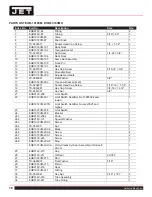
Page 16: ...8 1 1 4 4 19 TS 0060081 Hex Cap Screw 3 8 16 1 3 4 1 20 TS 0561031 Hex Nut 3 8 1 21 EHB916V 206 Limit Switch 1 22 EHB1018VM 207 Limit Switch Seat Ser No 13080024 and lower 1 EHB1018VM 207N Limit Switc...

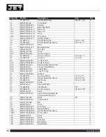
Page 17: ...Wheel 1 55 1 EHB916V 249 1 Handle 1 56 EHB1018VM 250 Seat 1018VM only 1 56 1 TS 0051051 Hex Cap Screw 1018VM only 5 16 18 1 2 56 2 TS 0720081 Lock Washer 1018VM only 5 16 2 57 EHB1018VM 252 Acme Scre...

Page 18: ...Coolant Pump 1 85 2 EHB916V 281 2 Pan Head Machine Screw 4 85 3 EHB916V 96 3 Way Coolant Block 1 85 4 EHB916V 281 4 Lock W Key 1 85 5 EHB916V 281 5 Lock W o Key 2 86 EHB1018VM 282 Bracket 1 87 TS 0070...

Page 19: ...8VM 319 1 Open Pin 1 8 x1 2 121 EHB1018VMH 320 Hydraulic Vise Assembly includes 121 1 121 5 1018VMH only 1 121 1 EHB1018VMH 320 1 O Ring 40 46 2 121 2 EHB1018VMH 320 2 Oil Scraping Ring UHS70 2 121 3...

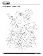
Page 20: ...20 Horizontal Band Saw SAW ARM ASSEMBLY EHB 1018VM 1018VMH...

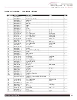
Page 21: ...in 5 x 30 1 17 TS 0732061 Lock Washer 3 8 1 18 EHB916V 18 Driven 1 19 EHB916V 19 Thrust Bearing Housing 1 20 EHB916V 02 Collar 1 21 EHB916V 21 Disc Spring 6 22 EHB916V 22 Copper 1 23 TS 0267041 Set Sc...

Page 22: ...w 3 16 x 3 8 2 75 EHB916V 75 Bracket 1 76 TS 0680031 Flat Washer 5 16 2 77 TS 0081031 Hex Cap Screw 5 16 x 3 4 2 78 TS 0081031 Hex Cap Screw 5 16 x 3 4 2 79 TS 0680031 Flat Washer 5 16 2 80 EHB916V 80...

Page 23: ...8 16 1 1 4 2 131 TS 0267071 Set Screw 1 4 20 3 4 4 132 TS 0270061 Set Screw 5 16 18 5 8 1 133 EHB1018V 133 Bracket R H 4 134 EHB1018VM 134 Slide 1 134 1 EHB916V 134 1 Scale 1 135 EHB916V 135 Screw 3 1...

Page 24: ...158 EHB916V 158 Special Knob 2 159 TS 0680041 Flat Washer 3 8 1 160 TS 0060031 Hex Head Screw 3 8 x 16 x 3 4 3 161 EHB1018V 161 Bracket 1 165 EHB916V 165 Round Head Screw 3 16 3 8 4 166 EHB916V 166 Co...

Page 25: ...HB1018VM 308 4 Relay Socket 1 308 5 EHB1018VM 308 5 Terminal Block 9 308 6 EHB1018VM 308 6 Electrical Plate 1 308 7 EHB1018VM 308 7 Round Head Screw 3 16 x 3 8 54 308 8 TS 0680011 Washer 3 16 54 308 9...

Page 26: ...1 308 5 EHB1018VM 308 5 Terminal Block 11 308 6 EHB1018VMH 308 6 Electrical Plate 1 308 7 EHB1018VM 308 7 Round Head Screw 3 16 x 3 8 62 308 8 TS 0680011 Washer 3 16 62 308 9 EHB1018VM 308 9 Power Cab...

Page 27: ...LOT LAMP MAIN MOTOR U1 V1 W1 U2 V2 W2 TO HYDRAULIC K1 K3 U3 V3 W3 CS2 PB3 K1 K3 K1 10 9 6 SOL1 HYDRAULIC K2 PB1 PB4 PB2 PB4 19 K2 CS1 PB5 K3 COOLANT PUMP LS4 LS4 LS5 5 7 13 8 9 4 3 12 14 CR 21 OP 27 F...

Page 28: ...LIGHT PILOT LAMP MAIN MOTOR UP DOWN U1 V1 W1 U2 V2 W2 TO HYDRAULIC K1 K2 U3 V3 W3 F1 F2 4 LS3 LS4 CS2 PB2 K1 1C 1C K1 19 10 9 5 7 PB5 SOL1 SOL2 K1 1C 14 15 1C PB6 PB7 PB6 PB7 17 18 SOL3 SOL4 K2 16 VI...

Page 29: ...29 EHB 1018VM EHB 1018VMH NOTES...

Page 30: ...30 Horizontal Band Saw NOTES...

Page 31: ...31 EHB 1018VM EHB 1018VMH NOTES...

Page 32: ...32 Horizontal Band Saw NOTES...

Reviews: