background image

10

8-in x 13-in Horizontal Cut-Off Bandsaw

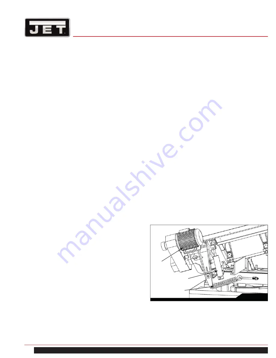
11.1  HYDRAULIC FEED CONTROL

The weight of the saw head provides the force needed to 
cut through the workpiece. The cut-off saw has a hydraulic 
cylinder that controls the feed rate of the saw.

The hydraulic feed control circuit consists of a single acting 
hydraulic cylinder (Figure 7) and a feed rate control (Figure 
4). The feed control cylinder resists motion in the downward 
direction to control the feed rate. The control cylinder offers 
no resistance when raised upward.

The feed rate control knob (Figure 4) controls the rate at 
which the saw head is lowered. The control knob (needle 
valve) controls the rate at which the hydraulic fluid is 
released from the hydraulic cylinder. When the needle 
valve is closed, the cylinder is locked. With the needle valve 
slightly open, the cylinder permits slow, or light, downward 
force. Opening the needle valve further increases the feed 
rate and applies more force to the saw blade and workpiece.

The needle valve is adjusted until the saw is operating ef-
ficiently. The efficiency of operation is usually evaluated 
by observing chip formation. Blade efficiency is further de-
scribed on the following page.

11.0  OPERATIONS

10.0  BLADE SELECTION           

The cut-off saw is delivered with a saw blade that is 
adequate for a variety of cut-off jobs on a variety of common 
materials. 

Refer to Figure 6 for the speeds recommended for various 
materials. These speeds, while appropriate for many 
common shop cutting needs, do not encompass the wide 
variety of special blade configurations (tooth pitch and set) 
and special alloys for cutting unusual or exotic materials.

A coarse blade could be used for a solid steel bar, but a 
finer tooth blade would be used on a thin-wall steel tube. 
In general, the blade choice is determined by the thickness 
of the material; the thinner the materials; the finer the tooth 
pitch.

A minimum of three teeth should be on the workpiece at all 
times for proper cutting. The blade and workpiece can be 
damaged if the teeth are so far apart that they straddle the 
workpiece.

For very high production on cutting of special materials, or 
difficult to cut materials such as stainless steel, tool steel, 
or titanium, you can ask your industrial distributor for more 
specific blade recommendations. The supplier that provides 
the workpiece material should be able to provide you with 
very specific instructions regarding the best blade (and 
coolant or cutting fluid, if needed) for the material or shape 
supplied.

10.1  BLADE BREAK-IN PROCEDURES

New blades are very sharp and, therefore, have a tooth 
geometry that is easily damaged if a careful break-in 
procedure is not followed. Consult the blade manufacturer’s 
literature for break-in of specific blades on specific materials. 
However, the following procedure will be adequate for break-
in of Jet-supplied blades on lower alloy ferrous materials:

1.  Clamp a section of round stock in the vise. The stock  
 

should be 2 inches or larger in diameter.

2.  Operate the saw at low speed. Start the cut with a    
 

very light feed rate.

3.  When the saw has completed 1/3 of the cut, increase  
 

the feed rate slightly and allow the saw to complete    

 the 

cut.

4.  Keep the hydraulic cylinder needle valve in the same  
 

position and begin a second cut on the same or 

 similar 

workpiece.

5.  When the blade has completed about 1/3 of the cut,   
 

increase the feed rate. 


Watch the chip formation until cutting is at its most    


efficient rate and allow the saw to complete the cut    

 (refer 

to 

Evaluating Cutting Efficiency

 section 11.2). 


The blade is now considered ready for use.

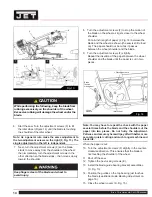
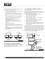
Fig. 7

Counterweight Spring

Hydraulic Cylinder

Drive 
Motor

Summary of Contents for Elite EHB-8VS

Page 1: ...ns and Parts Manual 8 in x 13 in Horizontal Cut Off Bandsaw Models EHB 8VS and EHB 8VSM JET 427 New Sanford Road LaVergne Tennessee 37086 www jettools com Ph 855 336 4032 Part No M 891015 REV C1 9 201...

Page 2: ...covers any defects in workmanship or materials subject to the limitations stated below This warranty does not cover failures due directly or indirectly to misuse abuse negligence or accidents normal...

Page 3: ...OR DEATH INJURIES TO PERSONS OR PROPERTY OR FOR INCIDENTAL CONTINGENT SPECIAL OR CONSEQUENTIAL DAMAGES ARISING FROM THE USE OF OUR PRODUCTS SOME STATES DO NOT ALLOW THE EXCLUSION OR LIMITATION OF INCI...

Page 4: ...re recommended Do not wear gloves 2 0 TABLE OF CONTENTS 1 0 WARRANTY AND SERVICE 2 2 0 TABLE OF CONTENTS 4 3 0 SAFETY WARNINGS 4 4 0 INTRODUCTION 6 5 0 SPECIFICATIONS 6 6 0 MACHINE FEATURES 7 6 1 MACH...

Page 5: ...orrect speed and feed rate Do not force a tool or attachment to do a job for which it was not designed The right tool will do the job better and more safely 26 Use recommended accessories improper acc...

Page 6: ...ck at 90 in 8 Round Stock at 45 in 8 Square Stock at 90 in 8 x 8 Speeds FPM Variable 80 310 Motor TEFC 1 1 2 Horsepower Capacitor Start 1725 RPM 1 Phase 115 230V prewired 115V 18 9A Blade Size in 1 x...
Page 7: ...ntrol panel blade tension blade tracking mechanism wire brush and the saw blade The drive motor is mounted on a pivoting plate that swings outward to provide drive belt tension The motor is fitted wit...

Page 8: ...the shipping skid discard any hold down devices Place the saw on the shop floor secure the saw to the floor using mounting anchors secured through four holes in the machine base Refer to Figure 1 for...

Page 9: ...is cut and the saw head is completely down Start Switch C press to start the drive motor The saw head must be in the raised position Power Light D indicates that machine is plugged in and the outlet c...

Page 10: ...ld be used on a thin wall steel tube In general the blade choice is determined by the thickness of the material the thinner the materials the finer the tooth pitch A minimum of three teeth should be o...

Page 11: ...rve the chips formed by the cutting blade If the chip formation is powdery then the feed is much too light or the blade is dull If the chips formed are curled but colored blue or straw colored from he...

Page 12: ...be submerged before operating to prevent damage to the pump 11 5 SETTING THE VISE FOR SQUARE CUTS The procedure for setting the vise for square cuts is identical to setting for angle cuts above except...

Page 13: ...king has been set and tested at the factory Adjustment is rarely required when the blade is used properly or if the blade is correctly welded If adjustment is needed 1 Using the blade tension handwhee...

Page 14: ...n the other direction so the blade stops then moves slowly toward the shoulder Note You may have to repeat the check with the paper several times before the blade and the shoulder cut the paper into t...

Page 15: ...is the same thickness as the rest of the blade If the blade is thicker at the weld the guide bearings may be damaged Fig 16 Disconnect the cut off saw from its electrical power source A B C D D E E F...

Page 16: ...assembly then the other as follows 1 Using a 3mm hex wrench loosen two set screws A securing the eccentric bushings 2 Using a 5mm hex wrench loosen two socket head cap screws D securing the carbide b...

Page 17: ...ht side of the eyebolt mount The saw can now be returned to service 13 0 MAINTENANCE 13 1 CHANGING BLADES Referring to Figure 21 pg 18 1 Raise the saw head A Set the feed rate control knob to zero to...

Page 18: ...efer to Blade Tracking Adjustment on page 14 if necessary 10 Close the wheel covers C 11 Put 2 to 3 drops of oil on the blade 13 2 CHANGING THE DRIVE BELT Referring to Figures 22 and 23 1 Set the arm...

Page 19: ...gs the bearings are lubricated and sealed periodic lubrication is not required Blade Guide Bearing the bearings are lubricated and sealed periodic lubrication is not required Upper Wheel Bushing six t...

Page 20: ...l 6 Insufficient blade tension 7 Operating saw without pressure on workpiece 1 Use a finer tooth blade 2 Try a lower blade speed 3 Decrease spring tension 4 Increase feed pressure hard spots Reduce sp...

Page 21: ...2 Replace with finer blade Blade is twisting 1 Blade is binding in the cut 2 Blade tension too high 1 Decrease feed pressure 2 Decrease tension on Blade Unusual wear on side back of blade 1 Blade gui...

Page 22: ...artment call 1 855 336 4032 Monday through Friday see our website for business hours www jettools com Having the Model Number and Serial Number of your machine available when you call will allow us to...

Page 23: ...23 EHB 8VS EHB 8VSM EHB 8VS SAW STAND BED PARTS BREAKDOWN...

Page 24: ...1 EHB8VS 6 1 Coolant Tank 1 6 2 EHB8VS 6 2 Hose 13x19 350mm 1 6 3 EHB8VS 6 3 Elbow PT1 2x1 4 1 6 4 EHB8VS 6 4 Coolant Pump 1 8HP 115 230V 1Ph 1 6 5 TS 0680021 Flat Washer 1 4 4 6 6 TS 081F052 Pan Head...

Page 25: ...Head Socket Screw M5x10 2 38 EHB8VS 38 Angle Scale 1 39 TS 1524021 Socket Set Screw M8x10 1 40 TS 1540061 Hex Nut M8 1 41 TS 1490081 Hex Cap Screw M8x45 1 42 EHB8VS 42 Front Moveable Vise Jaw 1 43 EH...

Page 26: ...1 402 EHB8VS 402 Swivel Bushing 2 403 EHB8VS 403 Control Column 1 405 TS 1490011 Hex Cap Screw M8 x 12 4 407 TS 1550061 Flat Washer M8 4 408 EHB8VS 301 Handle 1 409 EHB8VS 409 Control Box 1 411 EHB8V...

Page 27: ...27 EHB 8VS EHB 8VSM EHB 8VSM SAW STAND BED PARTS BREAKDOWN...

Page 28: ...4 Distance Set Rod 1 16 5 EHB8VS 16 5 Shaft 1 16 6 TS 154010 Hex Nut M16 2 0 1 16 7 EHB8VS 16 7 Scale 1 16 8 TS 1540071 Rivet 4 17 1S EHB8VS 17 1S Handwheel Assembly 1 17 2 TS 0680051 Flat Washer 7 16...

Page 29: ...4 1 61 TS 0680031 Flat Washer 5 16 1 62 TS 1505051 Socket Head Cap Screw M10x35 1 63 TS 2360121 Flat Washer M12 1 64 TS 2361011 Spring Washer M12 1 71 EHB8VS 71 Limit Switch Holder 1 72 TS 1534042 Pa...

Page 30: ...6 EHB8VSM 176 Round Head Cross Screw M5x10 8 177 TS 1503041 Socket Head Cap Screw M6x15 2 178 TS 1550041 Flat Washer M6 2 180 EHB8VSM 180 Pointer 1 181 EHB8VSM 181 Round Head Cross Screw M6x10 1 182 T...

Page 31: ...4 1 354 2 354 7 354 10 354 8 354 6 354 3 354 4 354 5 371 370 369 368 367 366 360 1 365 364 363 362 361 360 359 358 357 356 355 355 1 314 4 314 3 220 6 220 5 220 4 220 1 220 7 220 2 220 3 312 313 314 3...

Page 32: ...4 219 EHB8VS 219 Guide Bracket Left 1 220 1 EHB8VS 220 1 Valve 2 220 2 EHB8VS 220 2 Hose 6 2 220 3 EHB8VS 220 3 Straight Connector 2 220 4 EHB8VS 220 4 Hold Down Clamp 2 220 5 TS 2361061 Lock Washer M...

Page 33: ...2 318 EHB8VS 318 Slide Bar 1 319 TS 1524051 Socket Set Screw M8x20 4 320 TS 1492021 Hex Cap Screw M12x30 1 321 TS 2361121 Lock Washer M12 1 322 EHB8VS 322 Drive Shaft Washer 1 323 EHB8VS 323 Key 7x7x...

Page 34: ...4 9 Hose ID1 4 x2 2tx143cm 1 354 10 EHB8VS 354 10 Hose ID1 4 x2 2tx32cm 1 354 11 EHB8VS 354 11 Hose Clamp 2 354 12 EHB8VS 354 12 Cross Head Screw 2 355 EHB8VS 355 Hub 1 355 1 EHB8VS 355 1 Blade Tensio...

Page 35: ...5 14 Electrical Control Box Cover 1 5 15 EHB8VS 5 15 Electrical Control Box Base 1 EHB8VS ECB Electrical Control Box compound included 5 14 5 15 1 5 16 EHB8VS 5 16 Net Plate 1 5 17 EHB8VS 5 17 Cable...

Page 36: ...SB1 Emergency Stop KM2 PUMP Contactor L Signal FU1 24V 2A FUSE FU2 220V 1A FUSE FU3 110V 2A FUSE FR Overload M1 MAIN MOTOR M2 COOLANT PUMP MOTOR PE GROUND 2 2 0MM 1 M1 1 M2 FR PE 60HZ 1 L KM1 U1 W1 U2...

Reviews: