19
1. To adjust drag, loosen rear gib screw one turn,
and tighten front gib screw a quarter turn.
Rotate handwheel to check play. If still loose,
tighten front gib screw a bit more.
2. Repeat as needed until slide moves freely
without play.
3. When cross slide is properly adjusted, snug
rear gib screw. Do not overtighten; this will
cause premature wear on gib and mating parts.
Figure 11-3
11.2.3
Cross slide nut adjustment
The cross slide moves via a lead screw which drives
a nut. This can also be adjusted if backlash
develops. Turn cross slide handwheel left and right;
if there is a delay before any cross slide movement,
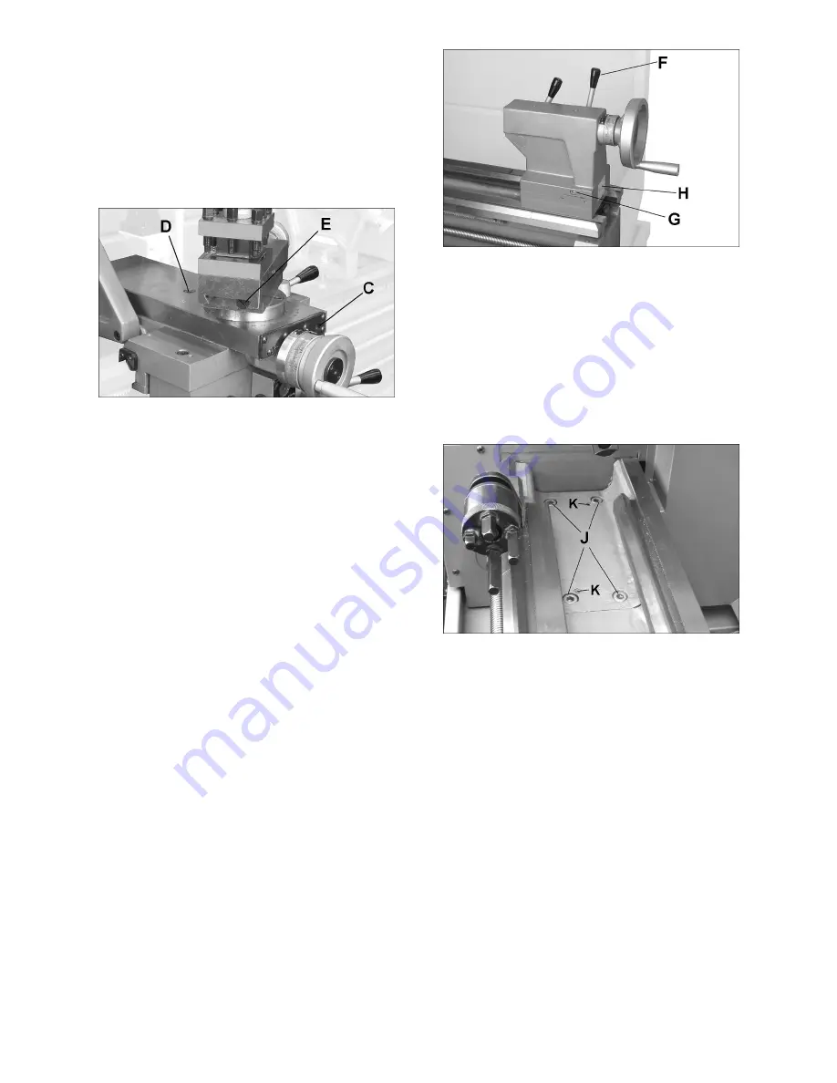
the nut needs adjusting. Tighten or loosen screw (D,
Figure 11-3) and move cross slide to verify setting.
11.2.4
Top slide gib adjustment
Gib screws are located at front and rear of top slide
(E, Figure 11-3). To adjust, use same method as for
cross slide gib above.
11.3
Tailstock adjustments
The tailstock can be offset to cut shallow tapers up
to 5° angle. See Figure 1-4.
1. Release clamping lever (F).
2. Alternately loosen and tighten front and rear
screws (G) to move tailstock laterally across
base. The scale (H) on end of tailstock indicates
amount of offset, and helps when re-centering.
3. Tighten clamp lever (F).
If the clamping force needs to be adjusted, remove
tailstock from bed and turn it over. Adjust the hex
nut as needed.
Figure 11-4
11.4
Gap section
To remove gap section (Figure 11-5):
1. Remove four socket head bolts (J) with hex
wrench.
2. Remove two tapered alignment pins (K) by
threading an M6 screw down into it, until the pin
is loosened enough to be pulled out.
3. Remove gap section.
Figure 11-5
To reinstall gap section:
1. Thoroughly clean bottom and ends of gap
section.
2. Set gap section in place and align the ends.
3. Insert tapered pins (L) into their holes through
gap and into lathe bed.
4. Re-insert the six bolts (A,B) and tighten
alternately until all are snug. Make sure gap
remains aligned with ways while tightening
screws.
Summary of Contents for EVS-1440B
Page 9: ...9 5 1 Machine dimensions and hole spacing Figure 5 1 Figure 5 2 ...
Page 23: ...23 13 0 Thread and feed chart Table 9 ...
Page 26: ...26 15 1 2 EVS 1440B Headstock Assembly Exploded View II ...
Page 27: ...27 15 1 3 EVS 1440B Headstock Assembly Exploded View III ...
Page 30: ...30 15 2 1 EVS 1440B Gearbox Assembly Exploded View I ...
Page 31: ...31 15 2 2 EVS 1440B Gearbox Assembly Exploded View II ...
Page 32: ...32 15 2 3 EVS 1440B Gearbox Assembly Exploded View III ...
Page 35: ...35 15 3 1 EVS 1440B Apron Assembly Exploded View I ...
Page 36: ...36 15 3 2 EVS 1440B Apron Assembly Exploded View II ...
Page 37: ...37 15 3 3 EVS 1440B Apron Assembly Exploded View III ...
Page 40: ...40 15 4 1 EVS 1440B Carriage Assembly Exploded View ...
Page 42: ...42 15 5 1 EVS 1440B Tool Post Assembly Exploded View ...
Page 44: ...44 15 6 1 EVS 1440B Tailstock Assembly Exploded View ...
Page 46: ...46 15 7 1 EVS 1440B Bed Assembly Exploded View ...
Page 48: ...48 15 8 1 EVS 1440B Cabinet and Panel Assembly Exploded View ...
Page 50: ...50 15 9 1 EVS 1440B End Gear Assembly Exploded View ...
Page 60: ...60 15 19 1 892035 Taper Attachment Assembly OPTIONAL Exploded View ...
Page 62: ...62 15 20 1 EVS 1440B Control Plate Assembly Exploded View ...
Page 64: ...64 16 0 Electrical Connections for EVS 1440B ...
Page 65: ...65 ...
Page 66: ...66 ...
Page 68: ...68 427 New Sanford Road LaVergne Tennessee 37086 Phone 800 274 6848 www jettools com ...


