11
3.1.3. SWITCH SPRINGS
• Ensure switch springs are not damaged or missing
NOTE: operation without either one of the springs is dangerous and is prohibited
3.1.4. LOAD CHAIN
• Check the load chain for proper lubrication
• Check the load chain for any damage, wear, or twisting
3.1.5. PUSH BUTTON SWITCH
• Check the case for cracks
• Does the push button work smoothly? Return of the push button should also be smooth
• Check for dirt or contamination around the switch
3.1.6. OVERALL OPERATION (Final check)
• Is the upper & lower limit switch functioning correctly?
• Is the brake functioning correctly?
• Are there any unusual noises caused during the up-down, transverse and travel movement of the hoist?
3.2. MONTHLY INSPECTION
NOTE: before the body is disassembled first perform the following:
1. Unload the hoist
2. Lower the chain until about 10 cm before the lower limit switch engages
3. Disconnect the power supply
3.2.1. MOTOR BRAKE
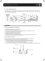
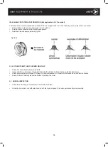
• Thickness of 531 lining
o
The minimum thickness of the 531 lining is 7.5mm. The brake disc must be replaced when the
thickness (Fig.16) is less than 7.5 mm. (Initial thickness is 8 mm)
• How to measure:
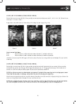
1. Remove all the connectors connected to A and B in Fig.17.
2. Remove 361 electric component cover case.
3. Pull and remove the insulated terminal shown (C) Fig.17.
(Wiring can be interchanged when reassembling).
The brake coil of 575V model has 3 black wires and 2 red.
Loosen the screws and remove.
(2 red lines can be interchanged when rewiring. The black
wire must be connected to the same terminal).
4. Remove 543 rubber brake cover and 5442 and 5443 nuts to
dismantle the brake assembly (Fig.17) The lining thickness
can then be measured remembering that the minimum thickness
is 7.5 mm. (Fig.16) Follow the reverse sequence to reassemble.
NOTE: Some models have only 1 lining with no 564b in use.
Figure 17
Figure 16


