43
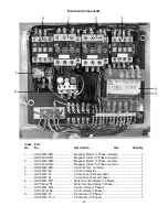
9.......... GH1440W-SQ2......................... Door Switch (not shown) ........... ...................................1
10........ GH1440W-SA1 ......................... Power On /Off Switch (not shown) .................................1
11 ........ GH1440W-SQ1......................... Brake Switch (not shown).......... ...................................1
12........ GH1440W-SB1 ......................... Off Switch (not shown) .............. ...................................1
13........ GH1440W-SB2 ......................... Jog Switch (not shown) ............. ...................................1
14........ GH1440W-HL ........................... Power Indicator Light (not shown) .................................1
15........ GH1440W-SA2 ......................... Coolant Pump Switch (not shown).................................1
16........ GH1440W-SQ3......................... Forward Switch (not shown) ...... ...................................1
17........ GH1440W-SQ4......................... Reverse Switch (not shown) ...... ...................................1
............ GHW-M1-1................................ Main Motor (1 Phase, not shown) ..................................1
............ GHW-M1-3 ............................... Main Motor (3 Phase, not shown) ..................................1
............ GHW-M2-1 ............................... Coolant Pump (1 Phase, not shown) .............................1
............ GHW-M2-3 ............................... Coolant Pump (3 Phase, not shown) .............................1
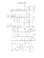
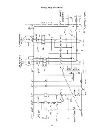
W Series Lathes Electrical Schematic Symbol Glossary
Symbol
Component
Location
SB1 .. ..................Off Switch........................................................................................Front Panel
SB2 .. ..................Jog Switch.......................................................................................Front Panel
HL .... ..................Power Indicator Light.......................................................................Front Panel
SA2 .. ..................Coolant Pump Switch ......................................................................Front Panel
SQ1.. ..................Brake Switch ............................................ Inside Bottom Cover-Headstock End
SQ2.. ..................Door Switch............................................................. Inside Change Gear Cover
SQ3.. ..................Forward Switch ...................................... Inside Front Panel (Right Of Gearbox)
SQ4.. ..................Reverse Switch ...................................... Inside Front Panel (Right Of Gearbox)
SA1 .. ..................Power On/Off Switch ...................... On Electrical Panel Cover-Rear of Machine
KM3 . ..................Coolant Pump Contactor ......................Electrical Control Box- Rear of Machine
KA .... ..................Control Contactor .................................Electrical Control Box- Rear of Machine
FR1 .. ..................Motor Overload Relay...........................Electrical Control Box- Rear of Machine
FR2 .. ..................Coolant Pump O/L Relay ......................Electrical Control Box- Rear of Machine
KM1 . ..................Magnetic Starter-Forward .....................Electrical Control Box- Rear of Machine
KM2 . ..................Magnetic Starter-Reverse .....................Electrical Control Box- Rear of Machine
TC.... ..................Control Transformer..............................Electrical Control Box- Rear of Machine
M1.... ..................Main Motor ............................................................Inside Stand-Headstock End
M2.... ..................Coolant Pump Motor.................................................Inside Stand-Tailstock End
Summary of Contents for GH-1340W
Page 3: ...3 Headstock Assembly I ...
Page 6: ...6 Headstock Assembly II ...
Page 8: ...8 Headstock Assembly III ...
Page 11: ...11 Gearbox Assembly I ...
Page 13: ...13 Gearbox Assembly II ...
Page 15: ...15 Gearbox Assembly III ...
Page 18: ...18 Apron Assembly I ...
Page 20: ...20 Apron Assembly II ...
Page 22: ...22 Carriage Cross Slide Assembly ...
Page 25: ...25 Four Way Tool Post Compound Slide Assembly ...
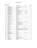
Page 27: ...27 Tailstock Assembly ...
Page 29: ...29 Bed Assembly ...
Page 32: ...32 Stand Assembly ...
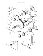
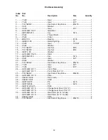
Page 34: ...34 End Gear Assembly ...
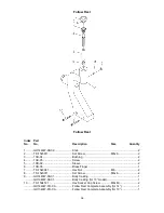
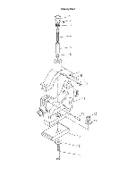
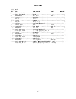
Page 38: ...38 Steady Rest ...
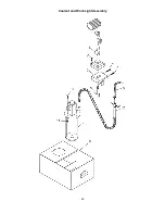
Page 40: ...40 Coolant and Work Light Assembly ...
Page 44: ...44 Wiring Diagram 1 Phase ...
Page 45: ...45 Wiring Diagram 3 Phase ...

