5
Index
Part
No.
No.
Description
Size
Quantity
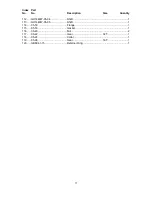
51........ GH1440W-04-54....................... Shaft ......................................... ...................................1
52........ GH1440W-04-53....................... Shaft ......................................... ...................................1
53........ GB1096-4X10 ........................... Key ........................................... 4x10............................1
54........ GB3452.9-10.6X2.65 ................ O-Ring ...................................... 10.6x2.65....................1
55........ GH1440W-04-55....................... Collar ........................................ ...................................1
56........ TS-1503031 .............................. Hex Socket Cap Screw ............. M6x12.......................18
57........ GH1440W-04-57....................... Collar ........................................ ...................................1
58........ GH1440W-04-58....................... Handle Body ............................. ...................................1
59........ 04-62 ........................................ Washer ..................................... ...................................1
60........ 04-90 ........................................ Indicator Disk ............................ ...................................1
142...... GB3452.9-25X2.65 ................... O-Ring ...................................... 25x2.65.......................3
159...... GH1340W-04-02....................... Name Plate............................... ...................................1
............ GH1440W-04-02....................... Name Plate............................... ...................................1
............ GH-1340W-3J.B.S .................... 3-Jaw Chuck (not shown) .......... ...................................1
............ GH-1340W-4J.B.S .................... 4-Jaw Chuck (not shown) .......... ...................................1
Summary of Contents for GH-1340W
Page 3: ...3 Headstock Assembly I ...
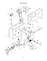
Page 6: ...6 Headstock Assembly II ...
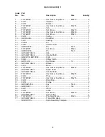
Page 8: ...8 Headstock Assembly III ...
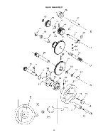
Page 11: ...11 Gearbox Assembly I ...
Page 13: ...13 Gearbox Assembly II ...
Page 15: ...15 Gearbox Assembly III ...
Page 18: ...18 Apron Assembly I ...
Page 20: ...20 Apron Assembly II ...
Page 22: ...22 Carriage Cross Slide Assembly ...
Page 25: ...25 Four Way Tool Post Compound Slide Assembly ...
Page 27: ...27 Tailstock Assembly ...
Page 29: ...29 Bed Assembly ...
Page 32: ...32 Stand Assembly ...
Page 34: ...34 End Gear Assembly ...
Page 38: ...38 Steady Rest ...
Page 40: ...40 Coolant and Work Light Assembly ...
Page 44: ...44 Wiring Diagram 1 Phase ...
Page 45: ...45 Wiring Diagram 3 Phase ...


