8
5.0
Uncrating
Open shipping crate and check for shipping
damage. Report any damage immediately to your
distributor and shipping agent. Do not discard any
shipping material until the Lathe is assembled and
running properly.
Compare the contents of your crate with the
following parts list to make sure all parts are intact.
Missing parts, if any, should be reported to your
distributor.
Read and understand the
entire contents of this manual before
attempting set-up or operation. Failure to
comply may cause serious injury!
5.1
Contents of shipping container
1 Lathe
1
Steady Rest (mounted on lathe)
1
Follow Rest (mounted on lathe)
1
6" Three Jaw Chuck w/ Top Reversing Jaws
(mounted on lathe)
1
8" Four Jaw Chuck with Backplate (strapped to
container)
1
12" Face Plate (strapped to container)
1 Backplate
1
Tool Box (p/n GH1440-TBCP)
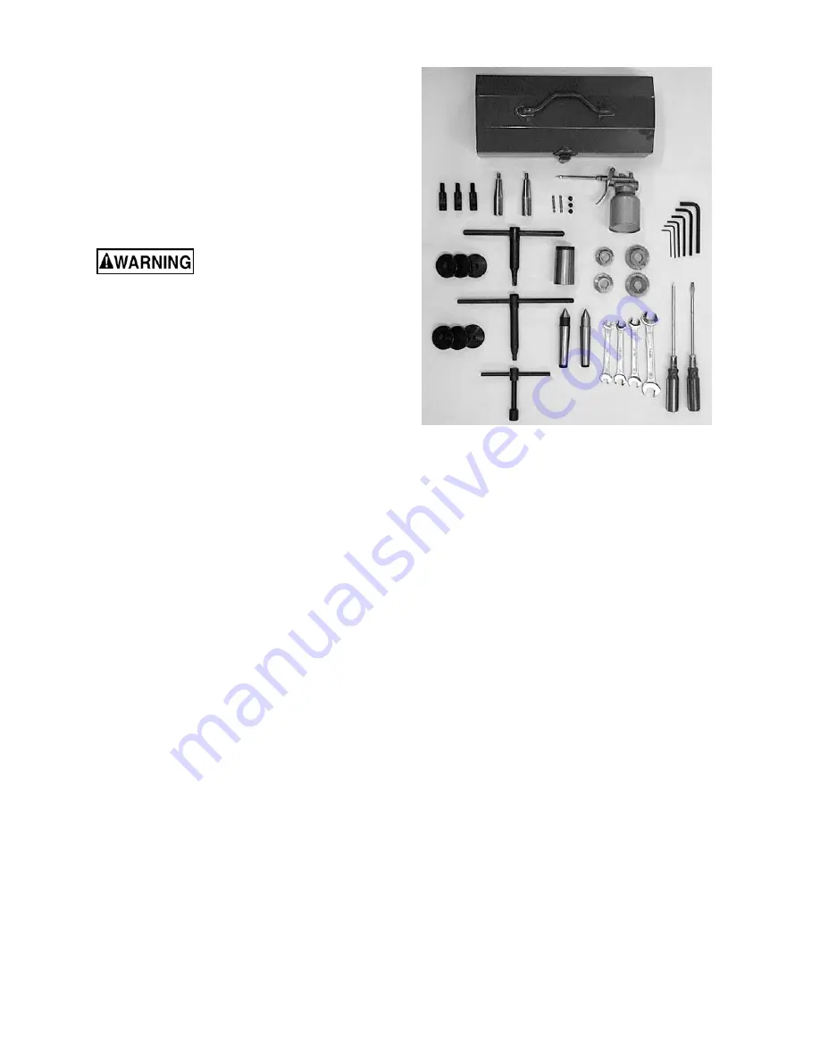
Tool Box Contents
(p/n GH1440-TBCP):
(Fig. 1)
1
No. 1 Cross Point Screwdriver
1
No. 1 Flat Blade Screwdriver
4 Open
End
Wrench
(9-11, 10-12, 12-14, 17-19mm)
7
Hex Socket Wrench (2,2.5, 3, 4, 5, 6, 8mm)
2 Shear
Pins
1
30T Change Gear
1
32T Change Gear
2
40T Change Gear
2 Handles
1
Can, Gray Touchup Paint
1 Oil
Gun
1 Live Center
2
No. 3 Morse Taper Dead Center
1
No. 5 to No. 3 Spindle Sleeve
6 Leveling
Pads
6 Leveling Bolts with Hex Nuts
2 Hex Socket Cap Screw
1 Chuck
Key
1
Key for Cam Locks
1 Tool
Post
Wrench
1 Taper Piece
1
Operating Instructions and Parts Manual
1
Product Registration Card
Figure 1
Summary of Contents for GH-1440
Page 23: ...23 14 1 1 Headstock Assembly I Exploded View ...
Page 26: ...26 14 2 1 Headstock Assembly II Exploded View ...
Page 28: ...28 14 3 1 Headstock Assembly III Exploded View ...
Page 30: ...30 14 4 1 Gearbox Assembly I Exploded View ...
Page 33: ...33 14 5 1 Gearbox Assembly II Exploded View D C B ...
Page 36: ...36 14 6 1 Apron Assembly I Exploded View ...
Page 38: ...38 14 7 1 Apron Assembly II Exploded View A D E C B A B C D E ...
Page 40: ...40 14 8 1 Saddle and Cross Slide Assembly Exploded View ...
Page 43: ...43 14 9 1 Top Slide and Tool Post Exploded View ...
Page 45: ...45 14 10 1 Tailstock Assembly Exploded View ...
Page 47: ...47 14 11 1 Bed and Shaft Assembly Exploded View ...
Page 50: ...50 14 12 1 Stand and Brake Assembly Exploded View ...
Page 52: ...52 14 13 1 End Gear Assembly Exploded View ...
Page 56: ...56 14 16 1 Steady Rest Parts List ...
Page 61: ...61 14 20 1 Accessories I Exploded View ...
Page 65: ...65 15 0 Electrical Connections 15 1 Wiring Diagram 1 Phase ...
Page 66: ...66 15 2 Wiring Diagram 3 Phase ...
Page 68: ...68 427 New Sanford Road LaVergne Tennessee 37086 Phone 800 274 6848 www jettools com ...


