10
6.0
General Description and Nomenclature
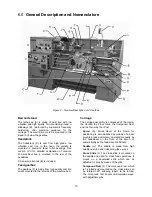
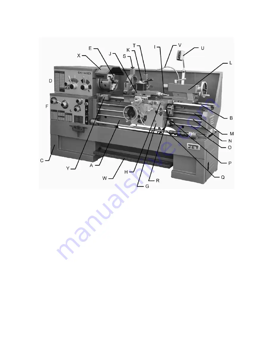
Figure 2 – General Description of ZX Lathes
Bed and stand
The lathe bed (A) is made of cast iron with low
vibration and high rigidity. Two precision-ground v-
slideways (B), reinforced by supersonic frequency
hardening, offer precision guidance for the
carriage. The main drive motor is mounted in the
stand (C) below the gearbox.
Headstock
The headstock (D) is cast from high grade, low
vibration cast iron. In the head, the spindle is
mounted in precision taper roller bearings. See
section 12.0
for detailed explanation of controls.
The electrical box is mounted to the rear of the
headstock.
A 3-Jaw scroll chuck (E) is included.
Feed gearbox
The gearbox (F) is made from high quality cast iron
and is mounted to the left side of the machine bed.
Carriage
The carriage assembly is composed of the
Apron
,
the
Saddle
, the
Cross Slide
, the
Compound Rest
,
and the four-way
Tool Post
.
Apron
(G).
Quick travel of the Apron for
positioning is accomplished by means of a bed-
mounted rack and pinion, operated manually by
the handwheel on the front of the apron, or
automatically by the feed direction handle.
Saddle
(H).
The saddle is made from high
quality cast iron and rides along the v-ways.
Cross Slide
(
I
). The cross-slide is mounted on
the saddle and used for cross feed operations. It
moves on a dovetailed slide which can be
adjusted for play by means of the gibs.
Compound Rest
(J). The compound rest, which
is T-slotted and mounted on the cross slide, can
be rotated 360°, allowing tapers to be turned.
The compound rest travels on dovetailed ways,
with adjustable gibs.
Summary of Contents for GH-1440ZX
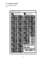
Page 26: ...26 T H R E A D I N G C H A R T I N I N C H ...
Page 27: ...27 m m M E T R I C T H R E A D I N G C H A R T M P M O D U L E P I T C H ...
Page 31: ...3 1 1 Stand Assembly Exploded View ...
Page 34: ...6 2 1 Brake Assembly Exploded View ...
Page 36: ...8 3 1 Bed Assembly Exploded View ...
Page 39: ...11 4 1 Headstock Assembly I Exploded View ...
Page 43: ...15 5 1 Headstock Assembly II Exploded View ...
Page 46: ...18 6 1 Headstock Assembly III Exploded View ...
Page 48: ...20 7 1 Headstock Assembly IV Exploded View ...
Page 50: ...22 8 1 Change Gear Box Assembly I Exploded View ...
Page 52: ...24 9 1 Change Gear Box Assembly II Exploded View ...
Page 54: ...26 10 1 Quick Change Gear Box I Exploded View ...
Page 57: ...29 11 1 Quick Change Gear Box II Exploded View ...
Page 59: ...31 12 1 Quick Change Gear Box III Exploded View ...
Page 61: ...33 13 1 Apron Assembly I Exploded View ...
Page 64: ...36 14 1 Apron Assembly II Exploded View ...
Page 67: ...39 15 1 Apron Assembly III Exploded View ...
Page 69: ...41 16 1 Carriage Assembly Exploded View ...
Page 73: ...45 18 1 Carriage Stop Assembly Exploded View ...
Page 75: ...47 19 1 Quick Change Tool Post Exploded View ...
Page 77: ...49 20 1 Tailstock Assembly I Exploded View ...
Page 79: ...51 21 1 Tailstock Assembly II Exploded View ...
Page 81: ...53 22 1 Steady Rest Assembly Exploded View ...
Page 83: ...55 23 1 Follow Rest Assembly Exploded View ...
Page 85: ...57 24 1 Coolant Work Light Assembly Exploded View ...
Page 89: ...61 26 2 Electrical Cabinet Breakdown 6 7 8 12 11 10 17 22 21 23 13 9 9a 20 18 3a 1 2 4 19 3 ...
Page 90: ...62 27 0 Wiring Diagram ...
Page 94: ...66 427 New Sanford Road LaVergne Tennessee 37086 Phone 800 274 6848 www jettools com ...


