16
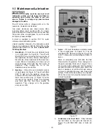
Figure 11
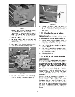
Saddle
– Daily lubricate ball oiler (A, Figure
12) on handwheel shaft with SAE 20W.
The anti-dust felt on both ends of the saddle
where it contacts the ways should be cleaned
weekly with kerosene. If the felt becomes
damaged, replace it.
5.
Compound Rest
– Daily lubricate two ball
oilers (B, Figure 12) on top of compound rest
with SAE 20W.
6.
Cross Slide
– Daily lubricate one ball oiler (C,
Figure 12 – opposite side) with SAE 20W.
Figure 12
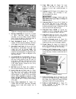
7.
Tailstock
– Daily lubricate one ball oiler (A,
Figure 13) on top of tailstock with SAE 20W.
Figure 13
8.
V-Belts
– Regularly check and adjust the
tightness of the v-belts to prolong their service
life. See
section 14.6,
Belt replacement
and
adjustment.
10.0
Coolant preparation
Follow coolant manufacturer’s
recommendations for use, care and disposal.
1. Remove access cover on tailstock end at the
rear base of the lathe. Make sure coolant
pump has not shifted during transport.
2. Pour four gallons (approximate) of coolant mix
into the chip pan.
3. After machine has been connected to power,
turn on coolant pump and check to see that
coolant is cycling properly.
4. Replace
access
cover.
11.0
Electrical connections
Electrical connections must be
made by a qualified electrician in compliance
with all relevant codes. This machine must be
properly grounded while in use to help protect
the operator from electrical shock and possible
fatal injury.
The main motor is rated at 7-1/2 HP (or 10HP for
model 2280ZX), 230/460V and comes from the
factory prewired at 230V. Confirm that power
available at the lathe’s location is the same rating
as the lathe.
Power is connected properly when rotation of the
forward-reverse knob (see E, Figure 15) to the left
position causes the spindle to rotate
counterclockwise as viewed from the tailstock. If
the chuck rotates in the clockwise direction,
disconnect the lathe from the power source, switch
any two of the three power leads (not the green
ground wire), and re-connect the lathe to the power
source.
Summary of Contents for GH-1440ZX
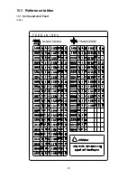
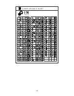
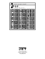
Page 26: ...26 T H R E A D I N G C H A R T I N I N C H ...
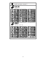
Page 27: ...27 m m M E T R I C T H R E A D I N G C H A R T M P M O D U L E P I T C H ...
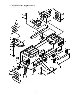
Page 31: ...3 1 1 Stand Assembly Exploded View ...
Page 34: ...6 2 1 Brake Assembly Exploded View ...
Page 36: ...8 3 1 Bed Assembly Exploded View ...
Page 39: ...11 4 1 Headstock Assembly I Exploded View ...
Page 43: ...15 5 1 Headstock Assembly II Exploded View ...
Page 46: ...18 6 1 Headstock Assembly III Exploded View ...
Page 48: ...20 7 1 Headstock Assembly IV Exploded View ...
Page 50: ...22 8 1 Change Gear Box Assembly I Exploded View ...
Page 52: ...24 9 1 Change Gear Box Assembly II Exploded View ...
Page 54: ...26 10 1 Quick Change Gear Box I Exploded View ...
Page 57: ...29 11 1 Quick Change Gear Box II Exploded View ...
Page 59: ...31 12 1 Quick Change Gear Box III Exploded View ...
Page 61: ...33 13 1 Apron Assembly I Exploded View ...
Page 64: ...36 14 1 Apron Assembly II Exploded View ...
Page 67: ...39 15 1 Apron Assembly III Exploded View ...
Page 69: ...41 16 1 Carriage Assembly Exploded View ...
Page 73: ...45 18 1 Carriage Stop Assembly Exploded View ...
Page 75: ...47 19 1 Quick Change Tool Post Exploded View ...
Page 77: ...49 20 1 Tailstock Assembly I Exploded View ...
Page 79: ...51 21 1 Tailstock Assembly II Exploded View ...
Page 81: ...53 22 1 Steady Rest Assembly Exploded View ...
Page 83: ...55 23 1 Follow Rest Assembly Exploded View ...
Page 85: ...57 24 1 Coolant Work Light Assembly Exploded View ...
Page 89: ...61 26 2 Electrical Cabinet Breakdown 6 7 8 12 11 10 17 22 21 23 13 9 9a 20 18 3a 1 2 4 19 3 ...
Page 90: ...62 27 0 Wiring Diagram ...
Page 94: ...66 427 New Sanford Road LaVergne Tennessee 37086 Phone 800 274 6848 www jettools com ...

